 Now that we talked about the basics of a pv system, load, battery basics and selecting a battery it is time for the PV module that gives the system the energy it needs to work. In this post we will discuss the basics of a PV module: Electrical characteristics and how it behaves when irradiation or temperature change. The second part of this post is about testing conditions for PV modules and what the data of the module mean in real life.
Electrical beaviour
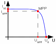
 The image on the left shows the characteristic curve of a PV module. There are three important points on that curve: In no-load condition the module gives you the open-circuit voltage U0 and the current is zero. When you short-circuit the module then the voltage goes to zero and the current reaches the short-circuit value of IK. Note that this current is not much higher than the desired operating current IMPP. This means that when you short-circuit a PV module you can’t damage it! On the other hand you cannot protect the circuit of the module with a fuse because the current will never rise enough for the fuse to blow.
The most interesting point in the diagram is the MPP: Maximum Power Point. Here you get the maximum of power from your module. In every other point of the characteristic curve the power will be less. This has nothing to do with changing irradiation. In this characteristic curve the irradiation is at a constant level. The power delivered by the module depends on the special point of the characteristic curve you operate it.
Variation of irradiation
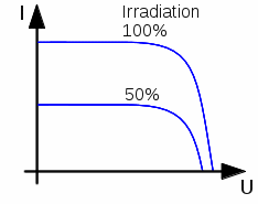
 The diagram on the left shows what happens when the irradiation of the module becomes higher or lower. The voltage varies only a little. The current is proportional to the irradiation: When irradiation goes down to 50% you will have only half of the current. On a cloudy day you have only around 10% the irradiation of full sunshine. Inside a room you often have only 1% of sun’s maximum irradiation. This is why standard PV modules often don’t work at all at room light conditions.
Variation of temperature
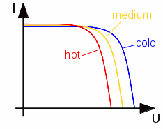
 The temperature of the solar cells inside the module also has an influence on the characteristic curve as shown on the left. The power of a standard crystalline silicon module decreases around 0.4% when the temperature increases 1K. This means you get less power from the module when the temperature is higher. The current stays almost the same. The variation is in the voltage. The voltage decreases when temperature rises and so does the power.
Standard Test Conditions (STC)
The electrical data of each module are measured under special standardized conditions to have comparable data of the different products that are available.
The Standard Test Conditions are:
1000W/m² Irradiation. This is approximately sun’s maximum irradiation on earth.
25°C Cell temparature. This is a standard for making measurement easy.
Spectrum AM1.5. Standard for measuring, comparable to sun’s spectrum on earth during goot daylight conditions
The electrical data of your module are always measured under Standard Test Conditions. This means that when you have a 40W module like this one you will get the 40W out of it only under Standard Test Conditions and (!) when the module is operated at MPP. In real life you normally don’t reach STC: When you have full sun (1000W/m²) then the cells are heated up and the cell temperature will be much higher than the 25°C in STC. As the module power gets less with rising temperature you will get only around 90% of the maximum power you find in the data sheet. This means that in normal use you probably will never get the maximum power from the data sheet. This is not because the module is faulty but because of the definition of STC.
This is not a problem to us when we have a standalone PV system with a battery. The battery collects the energy and saves it until it is used by the load. Therefore what matters is the amount of energy that comes from the module but not the power at the very moment.
12V module ???
When you look around for PV modules then you will find the so-called 12V modules. So what does that mean?
When we hear of a 12V module we would expect to have a module with a MPP voltage of 12V. But when you look at the data sheet of our example 40W PV module see that the actual MPP voltage is 18V. So what does that mean???
A 12V PV module is well-suited for a standalone system with a 12V lead-acid battery. Our “12V module” has its MPP voltage at 18V under STC. This means full irradiation at cell temperature 25°C. In reality we often have cell temperatures of 60°C to 80°C on full sunlight. So the real MPP voltage falls to around 15 to 16V. Then we have additional losses in our system: The voltage drop in the wires and the charge regulator is around 1V. So the resulting voltage is around 14 to 15V. Depending on what type of battery we use our maximum charge voltage is between 13.8V and 14.4V. Thus our module works close by it’s real MPP when the battery is high.
So a “12V module” doesn’t have it’s MPP voltage in the range of 12V but is well suited for a 12V system.
Regarding the module current this means: Our example 40W module that is called “40W 12V solar panel”doesn’t have a maximum output current of 3.3A (40W / 12V) but 2.2A (see data sheet, IMPP which is called there Imp). The module doesn’t have 40W at 12V voltage but has a maximum power of 40W under Standard Test Conditions and is well-suited for a 12V battery system.
So we see: a “12V module” doesn’t have a MPP voltage of 12V and: modules with a MPP voltage around 17V to 18V fit well to a standalone PV system wth a 12V battery.
In the next posts we will talk about where to put the module and how much energy comes from it.
Enjoy
heliosoph
