
This series of posts is a collection of my experience around connecting a Raspberry Pi and an Arduino through Modbus RTU via a RS485 serial connection. A lot of information can be found online – but not everything… This is the first part of this series with more to follow.
My idea is to build a data communication for sensors like temperature sensors and actors like motorized valves to control the heating system of my home. So this is nothing new and first of all it’s about choosing the right connection and data protocol. As I prefer a wired connection the choice is between Ethernet and a serial bus. In my usecase Ethernet needs more hardware like switches and cables and consumes more energy. Therefore, I chose the serial bus: Old school RS485 with a master-slave-communication. One telephone cable goes through all devices that are connected. As only one member can talk at a time this will be slower than Ethernet but this isn’t a problem at all when operating a heating system.
The serial connection: RS485
In the serial world there are a few classic connections that are mainly used. RS232 is a point-to point connection that connects two devices. There are two wires for the data transfer: one for sending (TxD) and one for receiving (RxD). TxD of the first device connects to RxD of the other device and vice versa. Transmitting and receiving can happen at the same time. This is called full duplex. RS232 is only good for connecting two devices and only for short distances of up to 15m. For more information see the Wikipedia article.
One of the other candidates was CAN-Bus. It has a three wire bus with a differential signal on two wires to improve immunity against electromagnetic noise and GND. All members share the same bus. This bus is a multi master architecture and allows for up to 32 members with standard drivers (or more with special drivers). The maximum length of the bus fits to my needs. One disadvantage is the small amount of data that can be sent in one message. CAN Bus is well suited for a decentral structure and still works (partially) when some of the bus members don’t work.
RS485 also allows up to 32 devices connected to the same bus (or more with special drivers) and allows long distances of some hundreds of meters. It also uses differential signals on the bus but has a master-slave structure with one single master that controls everything. This is what I am looking for: One Raspberry Pi that reads all the sensors and controls all the actors. The downside is: When the master is down there is no communication at all. But with a Raspberry Pi as the master this is rather unlikely. A good description of the RS485 bus is in Wikipedia. As only one member of the bus can talk at a time and everything happens on the same two lines the members mus switch between receive and send mode. The bus runs in half duplex mode.
Connecting the Raspberry Pi to RS485
As RS485 is a bus with a differential signal a special RS485 transceiver is necessary. I chose the MAX3430 from Maxim Integrated because it runs with 3.3V so it can be connected directly to the GPIO pins of the Raspberry Pi. So there is no need for level shifters. It also has a high protection level against transient voltage peaks and runs slower than others which helps in safe communication.
The Raspberry Pi has two UARTs: The PL011 main UART and the mini UART. Only the main UART has full features. This is why I always use it for serial communication. There is some configuration to be done: Turn off the Linux console on this UART and depending on the Raspberry Pi model switch between the two UARTs. This is described in detail in the Raspbery Pi docs.
Direction control basics
Connecting DI (Driver Input) with Tx and RO (Reveiver Output) with Rx of the Raspberry Pi’s UART is simple. But what to do with the DE (Driver output enable) and RE (Receiver output Enable)? This is where the fun begins 😉
First of all, we connect DE and RE because DE is active HIGH and RE is active LOW. When the signal on both pins is HIGH the driver which is the sender on the bus is enabled and the receiver is disabled. With the signal being LOW the driver is disabled and the receiver is enabled. This way, you can switch between send and receive mode with only one signal. In industrial applications only the transmitter (driver) switches on and off. The receiver is always on. Thus, the sending device receives its own signal and can compare it with the data that it has sent. This improves reliability and is a possibility to detect collisions on the bus. In my application I don’t use this feature and the receiver is switched on and off, too.
The RS485 transceiver needs three signals: Tx for sending data, Rx for receiving data and TxEnable to switch between send and receive mode. This is one big difference to RS232 where you don’t need a TxEnable.
Switching between send and receive mode obviously has to be done with the right timing. Enable send mode at the beginning of the message to send and disable it directly afterwords. Many software libraries are primarily designed for RS232, some (like pyserial) also have a RS485 mode that can handle the TxEnable signal.
Direction control: different solutions
As the serial data typically comes from a UART (Universal Asynchronous Receiver and Transmitter) that generates and reads the serial signals as a hardware device it would be straightforward when the UART also handles the TxEnable line. This is not the case as the UART is designed for RS232-like communication but not for RS485, probably because RS232 is much more widespread than RS485. Now there are some different solutions to this problem. A good summary is in the documentation of the minimalmodbus library.
A USB-to-RS485 adapter makes things easy if you are willing to send your data over USB. These adapters handle switching between send and receive mode all by themselves. On the software side there is no difference between a USB-to-RS232 or a USB-to-RS485 adapter. This works but to my eyes this is not a very straitforward approach.
Another idea is a serial-to-RS485 adapter that doesn’t need the TxEnable signal at all. This works in some cases. The trick is to use the Tx signal also as the TxEnable. With a HIGH signal the driver sends as expected. With a LOW signal the bus is idle and has ideally almost the same voltages on the bus as when sending a LOW signal. The idle bus should be stabilized with biasing, see the application note AN-960 from Analog Devices, chapter Fail-safe biasing. I’ve tested this already on a small bus with few members and it worked. It is simple to use because the data is sent and received by the UART and on the software side there is also no dfference to RS232. Maxim Integrated even has some RS485 transceivers with this feature integrated: E. g. the MAX13487E. But you have to keep in mind that the bus is driven only in one state. This is one form of automatic direction control.
Another path to automatic direction control is to derive the TxEnable signal from the Tx signal. When Tx starts then TxEnable is also turned on together with a monoflop that turns TxEnable off shortly after the end the Byte sent. Texas Instruments has published a reference design note with the famous NE555 as the monoflop. Personally, I think that this is the best of the hardware based solutions. The only downside is that you cannot switch the baudrate easily. But this won’t be a problem in a usual installation.
A UART doesn’t only offer Tx and Rx (send and receive) but also hardware handshaking signals that are used for handshaking on a RS232 connection. Would it be possible to use one of these for TxEnalbe? Turns out: It is when the timing is changed. The RTS signal (Ready To Send) can be modified by software to become the TxEnable we are looking for. This is where the software based solutions come:
Direction control with the Raspberry Pi
Many of the GPIO pins of the Raspberry Pi have more than one possible function. They can be changed to alternate functions:

GPIO17 can become RTS in alternate function 3. Then by software you can turn this pin to TxEnable. Unfortunately, this can work rather slow on the Raspberry Pi depending on the library you are using. Returning from send to receive mode can be delayed – some times more and some times less. This is a problem when the slave already begins to send its answer. Then there is a collision on the bus and the master doesn’t listen, anyway.
As we want to have Modbus running in the end we look for Modbus libraries:
For the minimalmodbus library that uses pyserial as the backend Wolfgang Hottgenroth did a great job analysing the timing problem.
Another possibility is to use libmodbus which is written in C. There is a python wrapper for it: pylibmodbus. And somebody even adapted it for the Raspberry Pi: pylibmodbus Rpi GPIO.
My approach to direction control
I do all my tests on a Raspberry Pi 3B. As described above I have to bring the PL011 UART to the GPIO pins and enable RTS. To enable RTS, I first tried to use a overlay as described in the Raspberry Pi forum. But I failed. Instead, alternate functions can be enabled in the config.txt file as described in the Raspberry Pi documentation. I ended up adding the following lines to /boot/config.txt:
# set PL011 as primary UART and disable bluetooth
dtoverlay=disable-bt
# enable RTS on GPIO 17
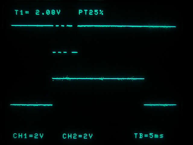
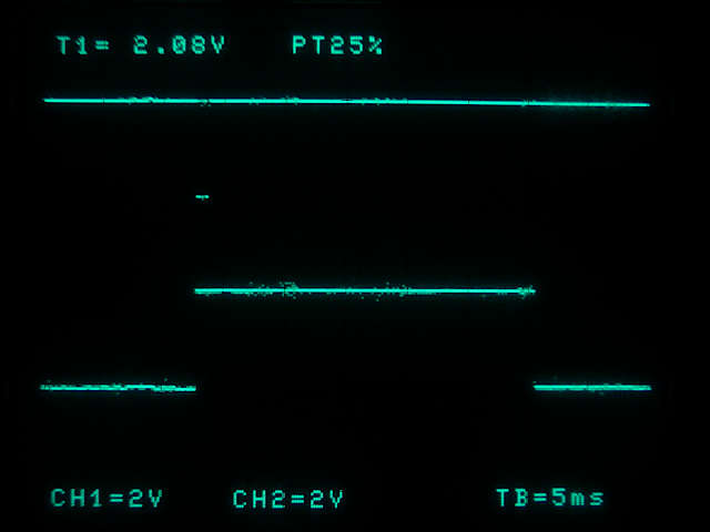
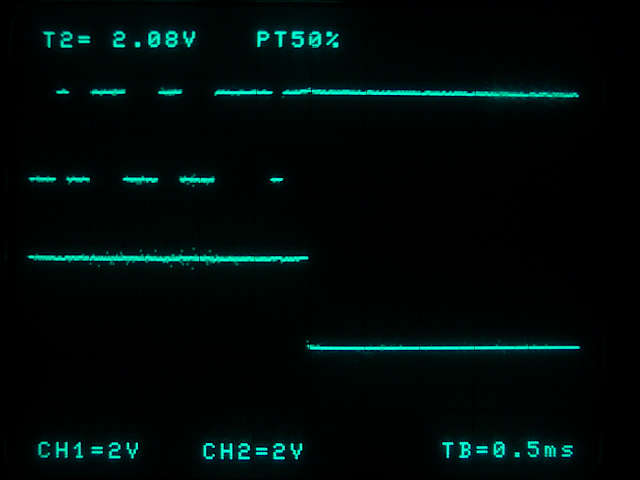
gpio=17=a3For pyserial the timing is according to what Wolfgang Hottgenroth found out. I wrote a small test script to see this behaviour on my scope. The first picture shows Tx (top) and TxEnable (bottom) at a very slow speed of 1200 baud. TxEnable starts at the right time but stops too late. The test script sends only one character: the number 5.
The length of the delay is not always the same. At a higher speed the total delay stays the same. This makes it even worse as more characters from the answering slave are swallowed.
The next step is to try the same with libmodbus that is written in C. When using libmodbus the entry in /boot/config.txt for GPIO17 can be deleted or cemmented out:
# enable RTS on GPIO 17
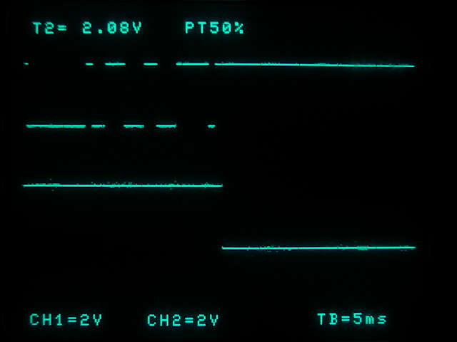
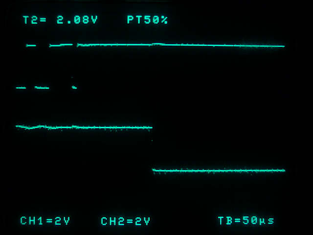
# gpio=17=a3For my tests I use the pylibmodbus Rpi GPIO version. It has a python wrapper and is able to use the GPIO pins of the Raspberry Pi. There are detailed installation instructions on that page. In the first step you install some additional packages: python3-dev, libffi-dev and dh-autoreconf with apt or apt-get. Then download libmodbus from the given source and configure, compile and install as described. To me it was helpfull to do configure, compile and install in three different steps. This helped me find some errors and get it installed afterwords. There is a working code example on this page at the end of the page. You only have to change the print statemant to print() für python3. The following picture is at 1200 baud, it’s the end of a modbus message. And tadaa, there’s no visible delay 🙂
The same with 9600 baud:
And also with 115200 baud:
The delay is around 140µs. At 115200 baud this equals to 16 bit or 1.6 characters. The minimum pause after the slave has received the message until it starts to send is 3.5 characters according to the modbus description. So this solution is fine for speeds up to 115200 baud.
If you use libmodbus directly in C instead of pylibmodbus this should be the same.
Now we have RS485 up and rnning on the RAspberry Pi. The next step is to set up the bus and have a look at the slave. This will happen in the next part of this series. Stay tuned!
Update Jan. 21
Some more tests showed that direction control with the modified pylibmodbus (see above) doesn’t work reliably. After booting the Raspberry Pi no direction control happens during the first two messsages. After that, it works for every message or every third message depending on the answer of the client 🙁
So I did what I wanted to avoid in the beginning (which was the cause for my experiments and for this article): Automatic direction control with the Tx signal combined with bus biasing. The Tx signal has to be inverted:
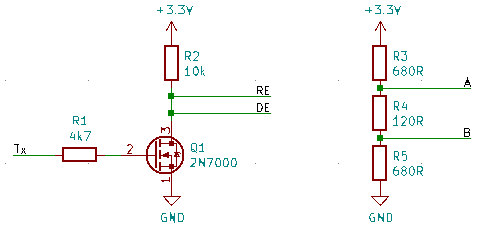
The MOSFET ist in a TO92 case because i do my tests on a breadboard. For a SMD version you can take e. g. a BSS138. On the right side are the resistors for biasing.
Now everything works fine 🙂 As direction control isn’t a software thing at the moment I can take whatever library I want on the Raspberry Pi. I already tested pylibmodbus and minimalmodbus with success.
Enjoy
heliosoph
Links
- Enable RTS to switch Tx/Rx for RS485 with overlays: https://www.raspberrypi.org/forums/viewtopic.php?t=241623
- Enable RTS (alternate pin function in config.txt: https://www.raspberrypi.org/documentation/configuration/config-txt/gpio.md
- Tests and timing details using RTS to switch Tx/Rx for RS485: https://maker.pro/raspberry-pi/tutorial/a-custom-rs485-hat-to-use-modbus-with-raspberry-pi
- Somebody on a similar road: https://aranair.github.io/posts/2017/10/30/programming-with-modbus-rtu-tcp-protocol/
- Modbus reference: https://modbus.org/docs/PI_MBUS_300.pdf