
In part 1 we have looked at the Raspberry Pi side of Modbus communication. Now it’s time for some facts about Modbus itself and the other end of the bus which happens to be an Arduino (sort of).
Modbus
Modbus is a industrial communication standard that uses either a RS485 bus for serial data transmission or Ethernet. In this series of articles we only take a look at serial communication but not at Ethernet. Serial communication has two versions, Modbus RTU (remote terminal unit) is widely used and described here. Modbus RTU sends data in binary form while Modbus ASCII sends ASCII characters. This makes the data stream itself human-readable but increases bus traffic. The Modbus protocol is described in detail in many places, e. g. in Wikipedia.
Comm basics and naming hazzle
On the RS485 bus only one device can talk at a time. To prevent data collisions the bus is impemented as a master-slave structure. The busmaster sends a data package to the slave and the slave then sends a data package back which is the answer. The master always initiates a communication and the slave sends the answer. To have only one slave talk at a time every slave on the bus has a unique address and replies only when his own address is in the address field of the coming data telegram.
Using the words master and slave now are called inappropriate language. The Modbus organisation has transitioned to the terms client and server and urges everybody to do the same. I talk about the old naming here because there can be a lot of misunderstanding about what is what. Is the old master the new server or the new client? And vice-versa.
When we think of big machine and small machine like in networks – the server is the big iron and the clients are the small machines on the desks we get it wrong. We would think that the old master is the new server because it is the “big” one on the bus as it does all the communication. But the naming is about who initiates the communication and who sends the answer. Therefore, the old master is the new client the same way as a client in a network sends a request and the server replies. So the former slave now is called the server. I have decided to use the old terms here to clarify the replacement.
Modbus knows only two datatypes: single bits and 16-bit registers. There are I/O bits called coils (named probably from the coils of the relays that switch the digital outputs). You can write to them and also read them back. The read-only bits are the discrete inputs. The same applies to the 16-bit registers: You can write and read back the holding registers and you can only read the input registers. The coils and discrete inputs are used for switching something on and of and for reading the state e. g. of a switch. The registers are for 16-bit numerical values like velocity, voltage, temperature… All the bits and registers have 16-bit addresses so you can have many of them. This makes it possible to read a lot of different data from a server.
Why Modbus?
One big advantage of Modbus (especially Modbus RTU) is that you have a minimal amount of hardware – one data cable going from the client to all the servers and RS485 transceivers. On the other hand, the protocol is simple and reliable. This is why I chose Modbus for my project.
Wiring the bus
The cable I use is standard telephone wire (in Europe e. g. J-Y(St)Y 2x2x0.6. It has two pairs of wires and is twisted to minimize EM noise. One pair (yellow and white) makes the bus lines A and B. The black wire is GND and the red one can be used as power supply for the bus members as long as they need only a small amount of current. All bus members are daisy chained and the bus has to be terminated with a 120Ω resistor. On the Raspberry Pi (client) side this is already done with the bus biasing network. The next thing you need are the RS485 bus transceivers for every bus member. There is a variety of different chips where most of them are pin compatible to each other. Choosing a chip depends on manximum transmission speed, with or without isolation and immunity against surge voltages. With the cable, termination and transceivers you are done.
Arduino as Modbus server
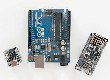
Now let’s talk about the other end of the communication bus: The server side. As this server can be a “small machine” I took something belonging to the Arduino universe: The Adafruit Feather M0 express. In terms of computational power an Arduino Uno R3 with its ATmega328P would be more than sufficient. But as all register values have to be stored in RAM the 2K of the ATmega328P are not enough. This is why i took a board with a SAMD21 chip with 32K of RAM.
Arduino software side
With the Raspberry Pi I encountered many unexpected problems with Modbus RTU. This is what I described in the first post. On the Feather it is better but also not without problems. Talking of Arduino I use the latest Arduino IDE to write and upload my code. There are a variety of different Modbus libraries for the Arduino. And there is also the “official” Arduino Modbus library. This is what I wanted to use. Turns out that this library doesn’t compile for SAMD21 chips. There is a workaround but in my experiments I saw that the library processes the request from the client but doesn’t send a valid answer. Some information is in this thread I opened: https://forums.adafruit.com/viewtopic.php?f=57&t=173295&hilit=modbus
So I decided for the Modbus-Master-Slave-for-Arduino library from {smarmengol]. The examples that come with the library give a good introduction on how to use it. It is rather simple but has all the commands needed. The data of all 16-bit registers and of all 1-bit inputs and outputs is stored in one big array. This array has to be of type uint16_t . In the examples this array is named au16data but you can give it any other name. The bit with the address 0 is bit 0 in au16data[0]. The bit with address 17 is bit 1 in au16data[1] and so on. But you can also read and write to au16data[0] as a 16-bit register. So you have to be clear in which address belongs to which register and type because the library doesn’t have any restrictions. It simply maps the bits to bits of the same array that also holds the 16-bit values. And it doesn’t distinguish between read-only and read/write. All locations in this array are read/write.
Links
- The features of some of the arduino libraries are described here: http://domoticx.com/arduino-library-modbus/