
 A standalone PV system begins with thinking about the load. So let’s talk about our load: The characteristics of the load determine all the components of the PV system because it must be designed to feed the load so that everything works the way we want it to.
In the first part of this article we will talk about choosing the appropriate system voltage. The second part is about how much electricity is consumed and how to optimize the system in a way that it needs less energy but still is fully functional.
System voltage: 12V
The system voltage is the nominal battery voltage which is also the supply voltage for the load. With lead-acid batteries we have 6V or 12V. 12V is a very common standard. You can get all the PV components for a 12V system like batteries, modules and charge regulators. Also many devices are available that run on 12V like motors, pumps, relays, lamps and whaterver. The arduino can also run directly on 12V as long as you don’t have to supply too much current on your I/O pins. If the devices you want to connect to your arduino run on 12V then make the system voltage 12V. If you want to build a PV system with off-the-shelf components then make the system voltage 12V. The big advantage of 12V is that you get everything you need for the system and there are lots of components that are very reliable. This enables you to build a properly working PV power supply with little effort.
System voltage: 6V
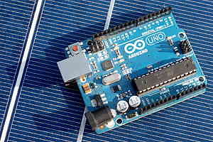
12V has many advantages but there is also a drawback. This becomes obvious when you see what happens in the power supply of your arduino board: The voltage the arduino actually runs on is 5V. The voltage regulator on the board reduces the input voltage (e. g. 12V) to 5V. This means that the difference of 7V gets lost in the regulator. This is more than half of the supply voltage. A arduino Uno R3 board without anything connected to the I/O pins consumes around 46mA of current when connected directly to +5V (via USB connector). The power is 46mA x 5V = 230mW. When connected to 12V the supply current is around 48mA and the total power is 48mA x 12V = 576mW. So your arduino consumes 230mW and has additional losses due to voltage regulation of 576mW – 230mW = 346mW. In other words: 60% of the input power from our 12V supply is dissipated in the voltage regulator. This is due to the big difference between the supply voltage of 12V and the 5V needed by our arduino.
So I was thinking about making the system voltage 6V. Then the power dissipated in the regulator would go down from 346mW to around 48mW and only 17% of the input power would be lost in the regulator. Total power consumption would be 288mW instead of 576mW at 12V. This means that your PV module and your battery will have only half the size as in a 12V system. The main drawbacks of this are that it’s hard to get the right components for the PV system and that you can’t use the voltage regulator on the arduino board. We will look at this in more detail in a later post.
The summary is: When you have only 5V devices in your application then you can think about making a 6V system. You will need a custom charge regulator and another voltage regulator for the arduino.
Calculating electricity consumption
The amount of electricity consumed is important for choosing the right battery and PV module. We will calculate it in ampere-hours (Ah) per day. This is the product of supply current and time. Our arduino board has a supply current of 48mA. In 24 hours you need 0.048A x 24h = 1.15Ah when it is active the whole day.
Additionally we have the other components like a motor, a pump, LEDs or whatever. The calculation is always the same: Current x time gives the ampere-hours.
An example is the watering system for my garden that I built. It is very easy: A arduino and a 12V DC water pump that runs for 7.5 minutes each day. The pump runs at a current of 0.8A. So the pump consumes 0.8A x 0.125h = 0.1Ah. You should know the current and the runtime per day of all your components. When you don’t know the exact runtime then estimate is as good as possible. When you don’t know the supply current then take a amperemeter and measure it.
Calculate the electricity consumption of all your components including the arduino and then take the sum of them all. This is the total amount of electricity that will be drawn from the PV system. In our example it is 1.15Ah + 0.1Ah = 1.25Ah.
And what about the energy? In these posts we deal with ampere-hours for practical reasons: It is (in my opinion) easier to calculate and the capacity of a battery is also given in ampere-hours. If you want to calculate the amount of energy that is consumed: Power x time gives the watt-hours. 1000 watt-hours are 1 kilowatt-hour. This is what you pay for when grid-connected. Because voltage x current gives the power you can calculate this also with the sysem voltage the current and time: voltage x current x time gives the energy in volt-ampere-hours which is the same as watt-hours. This shows you: Reducing the system voltage from 12V to 6V with the same current drawn reduces the energy consumption by 50%.
Reducing electricity consumption
After calculating the total amount of electricity you can see which parts of your system consume a lot of energy. In our example it is the arduino that uses almost all the energy. Now it’s time to look how you can make the system more efficient.
You can use motors, switches, lamps with higher efficiency to reduce electricity consumption. E. g. take LEDs instead of bulbs or a MOSFET instead of a bipolar transistor and so on. Or you can do things in another way than before. In our example a drip irrigation is more efficient than e. g. a sprinkler. This saves a lot of water and also electricity for the pump. There are thousands of possibilities of making a system more efficient.
Concerning the arduino there are also many ways to reduce electricity needs a lot. Nick Gammon wrote a very interesting article about reducing arduino’s power needs. Look at: http://gammon.com.au/power. Thanks you Nick for this great job!
In our example it would save lots of energy when setting the arduino to sleep and waking it up by interrupt from a real time clock e. g. DS1307 once a day.
Reducing electricity consumption is the first and most important step to a cost and resources effective and efficient power supply for our devices.
In the next posts we will talk about the battery that stores the energy to enable 24/7 operation. The first post is about battery basics and the second post is about how to select the battery that fits best to our needs. Also read about PV module basics, PV module dimensioning, the charge regulator and practical hints for building a system.
Enjoy
heliosoph
proof reading type correction:
-section: Calculating electricity consumption
-paragraph: 2
– unuseable wording: ” …. calculation is always the same: Power x time gives the ampere-hours…..”
– corrected wording: “… the same: current x time gives the ampere-hours…..”
– suggested additional sentence: Volt-ampere-hours = Watt-hours
Hi Gary D
thank you very much for your comment! It shows me that people really read the stuff I wrote and gives me the chance to improve it. Sometimes proofreading twice is not enouth. I corrected the things in the post and added a small paragraph about energy calculation.
Thanks again
heliosoph
hi.my project is purely dc,batteryless small photovoltaic power system.solar panel has output 12v/10w. but arduino work on 5v. how can I set connection solar panel and arduino? what can I do for this voltage difference?
When you use an arduino board like the Uno R3 the voltage regulator in onboard. You can directly connect to your pv module when the open circuit voltage is not too high. You can find additional information on the arduino homepage when you look in the board documentation.
When you have a standalone chip like the Atmega328P you could take one of the common 3-pin voltage regulators like 7805 or 78L05. Don’t forget the additional capacitors between the pins.
Regards
heliosoph