
 Our stand-alone PV system is almost complete now: We have the module the battery and our load. Now it’s time to connect the devices. Therfore we need the charge regulator. All other components are connected to it. The charge regulator has two functions: It limits the charging current to get the battery charged in an optimal way and to prevent overcharge. The second function is to cut off the load when the battery runs empty to prevent a deep discharge. This is all done to extend battery’s life. In this post we will look at how these functions are built in hardware and what are the different concepts of charge regulators. We will also talk about choosing the “right one”.
Connecting the solar panel to the battery
Standard
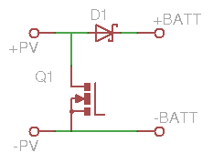 The “standard” charge regulator directly connects the PV module to the battery over a diode. The operating point of the module is determined by the battery voltage: The actual operating voltage of the module equals the battery voltage plus the forward voltage of the diode plus the voltage drop in the wires. The disadvantage is that the module doesn’t work in the optimal point: MPP (see PV module basics). The advantage is: There are only few components. This is the reason why these charge regulators are somehow standard. The diode normally is of Schottky type for reduced losses.
During normal operation (when the battery isn’t almost or completely full) the power MOSFET Q1 is in the off state. When switched on Q1 shorts the module and the current doesn’t flow to the battery. Now you see what D1 is for: When Q1 is on the diode prevents shorting the battery. Shorting the module isn’t a problem both to the module and the MOSFET (see PV module basics) but shorting the battery would at least kill the transistor. Q1 is driven with a PWM signal and so the effective battery current can be regulated from the actual module current down to zero. This way the battery’s charging current is controlled. As the regulating element Q1 is in parallel to the solar panel this type is also called parallel charge regulator.
For a small PV system like most of the arduino projects this type of charge regulator is the “right one”. These charge regulators are very wide-spread. A big advantage especially in a small system is the low quiescent current they need. This keeps system losses low although the PV module isn’t in MPP.
MPP regulator
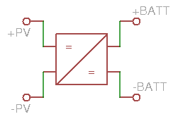 To avoid the disadvantage of the standard parallel charge regulator there are MPP regulators that have a DC/DC converter between the module and the battery. This makes it possible to have the module always operate in MPP and so giving maximum power into the system. The disadvantages are the losses in the converter and the higher quiescent current due to the much more complex design. They are also much more expensive than a standard charge regulator. MPP regulators can be a good choice in big systems especially when they have to work during winter time (= high MPP voltage). Here is an example for a somehow “big iron”. [timnolan] has built a MPP charge regulator with a arduino from scrath. His documentation shows the details of his work so you can have a in-depth look into it. In a big system another advantage of the MPP regulator becomes viable: As the voltage of the modules is independent of the battery voltage you can use standard solar panels for grid-connected systems and even connect them in series. These modules are much cheaper (per Watt) than the small “12V” modules and the wiring is easier.
Connecting the load to the battery
A charge regulator has two terminals for the load. They are connected to the battery terminals via a switch. This switch can be a relay contact or an electronic switch, normally another MOSFET. With this element the load can be switched on and off. During normal operation (battery not empty) the switch is on and the load is feeded. When the battery is empty the load is turned off to save battery’s life.
Charge regulation and overcharge protection
The charge regulation keeps the battery voltage at a constant level to prevent overcharging the battery. The exact value of this maximum charging voltage depends on the type of battery you want to use. For many gel oder AGM lead-acid batteries the maximum charging voltage is 13.8V and must not be exceeded to prevent H2 and O2 production. For flooded lead-acid batts the maximum charging voltage should be 14.1V. To prevent separation of the liquid electrolyte-water solution you can increase the voltage to 14.8V for some houres every three or four weeks. This is done by some (bigger) charge regulators. Some of the charge regulators can be configured for gel oder flooded batteries. Otherwise be careful to choose the one that fits to your battery technology.
Preventing deep discharge
The load is cut off when battery voltage drops down to 11V. At this point the battery is empty. After cutting off the load the battery voltage can rise to around 11.5V to 12V over time without charging. Knowing this the charge regulator turns on the load when the battery voltage is as high as 12.5V. Now the battery is already partly charged and can feed the load again without being switched off again immediately. This can be an enormous problem for the load because during a bad-weather phasis charging the battery up to 12.5V can take some days (worst case). Therefore you should bring always enough energy into the system to prevent the load being cutted off.
Choosing a charge regulator
The following points must be considered when choosing a charge regulator:
Standard or MPP: Normally Standard. MPP only in big systems.
System voltage: The same as the nominal battery voltage (e. g. 12V)
max. charge current = max. current from your module(s)
max. load current = maximum current your load needs
Battery type: see above
Quiescent current: Should be as low as possible because this is part of the losses in your system. The quiescent current of the charge regulator is like a load that is turned on 24/7.
additional functions: according to your needs / wishes, e. g. showing battery voltage, currents or your battery’s state of charge.
Now these are all the basic components or your PV system (ok, you also need some wires and a fuse). In the next post there will be some practical hints for building a real system including wiring and fusing.
Enjoy
heliosoph
12v means a lot of loss in a standard uno board to get it to 5v. better use a charge regulator that has a 12v and a 6v output.
have you found a way to put a 6v based system together?
Hello and thanks for your comment.
I chose the system voltage depending on the voltage the load needs. Concerning the arduino reducing power consumption can easily be done by not using the arduino board and having a standalone ATmega. For a very minimalistic approach look at . There you will find a lot of info about how to reduce energy consumption.
Best regards
heliosoph