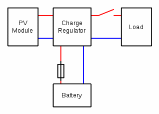
 In this post we will talk about some practical topics when it comes to building a real standalone PV system. We know the basic function of the system, about the load, we know the battery basics and selected a battery. We talked about what the PV module does and we looked for a module for our project. We also have a charge regulator. Now we will put this all together and connect the components.
Short circuit protection
In every electrical system it is very important to prevent a short circuit. In a PV system there are two different sources of energy and thus short circuit protection must be handled in two dfferent ways.
Preventing a short circuit of the battery
 Shorting the battery is always bad because it can provide a very high current while shorted depending on the size of the battery. This can kill all the components where the current flows and can also cause sparks and fire. To prevent this install a fuse near the battery. This fuse is connected directly to the plus terminal of your battery. So everything behind the fuse is protected. Some charge regulators have a fuse integrated in the regulator’s case. This leaves the wiring between the battery and the charge regulator unprotected. The max current of the fuse must be higher than the maximum load or module current.
Preventing a short circuit of the solar panel
In PV module basics we talked about shorting a PV module and we saw that this isn’t a problem to the module. In the charge regulator section we saw a parallel regulator shorting the module even in normal operation. So why should we prevent shorting the module???
The good thing about shorting a module is that the current rises only 15 to 20% over the normal MPP current. So you don’t damage erverything as when shorting the battery. But the good thing is also the bad thing: As the current doesn’t rise a lot you cannot do short circuit protection with a fuse. This means when you have a short circuit due to e. g. damaged module cables then the current will continue to flow until darkness. When your cable is squeezed and you have a contact between plus and minus with a relatively high contact resistance you will get high temperature at this point due to power dissipated in the contact resistance. This will damage your cable more and more and can even cause fire.
Shorting the module is more dangerous in bigger systems. When you have something like a 0.5W panel that gives you around 20mA of current there won’t be much of a problem. With a 20W module your max. current is more than 1A. In an unattended system this can cause problems. And 150W solar panels will give you up to 8A you will probably have serious problems when shorting the panel in an uncontrolled (and unwanted) way.
To prevent this the only way is to make a short-circuit proof installation. This means: don’t have plus and minus of the module in the same cable. Use two seperate cables with only one lead and with double isolation, one for plus and one for minus. This applies only for the wiring between the module and the charge regulator.
Wiring and minimal cable losses
First of all the diameter of the wires must be big enough to carry the maximum current safely. This is the case in every electrical installation. In a PV system also look for the losses of the wires. When the components of your installation aren’t all at the same place you have to care about this. Here you find a calculator that tells you the size of your cable that is necessary to reach losses between 1% and 5%. Note that the “length of cable run” is the distance e. g. between the PV module and the charge regulator. The calculator sums up plus and minus leads.
The same applies also to the connection between the charge regulator and the load. Normally you put the charge regulator near the battery so you don’t get considerable losses between these two components.
What you see is: 12V is only good in a small system with short distances between the components. When you have longer distances you should take a higher system voltage like 24V. Doubling the voltage divides the wire cross section by a factor of 4 with the same losses.
When you have your cable outdoors take a type with UV resistant insulation. Otherwise the sun will kill the insulation over time and you can get a dangerous short-cut.
The battery
Put the battery at a place where temperature doesn’t rise and fall too much. Self-discharge increases with temperature. When the ambient temperature is below 0°C you can have a problem with freeze of the electrolyte in flooded batteries depending on the battery’s state of charge. And never (!) put the battery in an airtight enclosure. Flooded batteries produce some H2 and O2 during charge. Also sulfuric acid fume leaves the battery depending on temperature. Some flooded batteries have a small flexible tube to lead the gas outside the compartment. This is especially important to prevent corrosion of other components near the battery caused by the sulfuric acid fume. When you have a VRLA type battery then nothing leaves the battery in normal operation. But when you overcharge it then the safety valve will open and will let explosive and corrosive gas leave the battery.
Also care for the weight of the battery. A 12V 100Ah is around 35kg. The place where you put is must be able to carry that load.
Where to put it all (summary)
On a small system you often put all the components at the same place. Battery and charge regulator are shaded by the solar panel. When temperature rises and falls too much make a box for the battery and the electronic components and use some insulation material. When you have your arduino handy you could think about monitoring the battery temperature.
For a bigger system look for a battery place that is as close as possible to the PV module and to the load. Always try to keep the cables short. This can save you a lot of money and effort. The module should be outside at a sunny place and the module cables must be UV-resistant. Think about venting and the weight when choosing the place for the battery. The charge regulator normally is near the battery. The charge regulator can tell you also about the battery’s state of charge and some other data and so it should be visible to you.
Hoping that this gives you enough information to build a standalone PV system to power your arduino project.
Enjoy
heliosoph

Great post. Its a great use of the arduino. Very nice.