
 In my “minimalistic standalone ATmega328 powered by a capacitor” project I was walking from the start through first tests, reducing consumption, optimized tests and adding a RTC. The RTC has let me learn a lot about waking up from sleep via interrupt.
Now one more component is due to come: external EEPROM to extend data memory. As I’m hoping to extend total uptime more I probably will run out of EEPROM memory when keeping the basic example (reading one ADC channel once a second and writing data to EEPROM). Furthermore, when it comes to practical use of the system, internal EEPROM is too small also.
24AA256
This is the EEPROM type I chose for the system. It has a supply voltage range from 1.8V to 5.5V and I2C bus connection. These are the two most important points for taking the 24AA256. Of course, it is a low power device. Furthermore, it has a page write mode where up to 64 bytes can be written at once. This could be a possibility to reduce total write time (and also total run time of the controller) to save power. Let’s look if this is possible…
I2C connection
Microchip Technology Inc.
On the left you see the pinout of the 24AA256 in DIP case. This is what we use on our breadboard. Connection of the device is very simple:
- Vcc is Vcc 😉
- Vss is connected to GND
- SCL and SDA are the two I2C wires. They are connected to A4 and A5 of the ATmega328 (arduino I2C standard) in parallel to the RTC. Pullup resistors are no more necessary as we already have plugged them while connecting the RTC.
- WP is a write protection. We don’t need it and connect this pin to GND.
- A0 through A2 can be set as individual device address when more than one EEPROM chip is used. We connect them all to GND. This gives us the I2C device address 50hex.
Talking to 24AA256
As I’m not the first one to connect the 24AA256 to an arduino chip there are several descriptions out there on how to read and write I2C EEPROM like here and here. Some of them are a bit outdated. So I was playing around with the Wire library that provides the I2C communication. Then luckily I found the I2C_EEPROM library from [robtillaart] that does all the communication with the 24AA256 and similar devices. This makes writing the sketch a snap!
First result
 In this test we have the same behaviour as when we were writing to the internal EEPROM. Once a second one AD channel is read and two bytes of data are written to EEPROM. Doing exactly the same thing but writing to the 24AA256 extends total uptime to 990s (!). This is 16.5 minutes 🙂 So presumably the 24AA256 writes faster than the internal EEPROM. To do a check we measure the duration of one wake-up cycle. Therefore a digital pin is used as output and set to HIGH directly after waking up and then set to LOW again before going to sleep. The measurements are: 5.6ms with 24AA256 and 3.8ms with the internal EEPROM. So obviously our presumption is wrong…
Measuring supply current
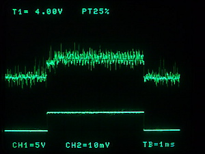 So now it’s time to look further into the details. Therefore we sense supply current with a resistor and display it on the scope. On the left you see what happens while writing to the 24AA256. The lower trace (channel 1) shows the output that tells us when the controller is running (HIGH) or sleeping (LOW). Channel 2 is the supply current. Although the signal is rather noisy (probably because of the nearby computer) we can see what is happening. Supply current is around 12mA when the controller is running (and part of the time writing to the 24AA256). This is what we expect but at the moment it isn’t visible why there should be less power consumption as when writing to the internal EEPROM of the ATmega328P.
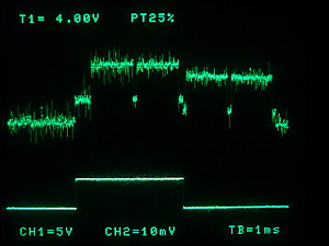 Let’s have a look at what’s going on while writing to the on-chip EEPROM. At the beginning of the wake-up cycle the controller does it’s job: reading the ADC. Then supply current rises up to 20mA when data is written to EEPROM. The first byte is written. Then the second write cycle (the second byte) is initiated. Now the controller goes to sleep and the write cycle is finished while the rest of the controller is already sleeping. We see that with the internal EEPROM supply current is higher than with the 24AA256 and also the total duration is longer. This means that energy consumption is reduced when the internal EEPROM is replaced by an external one like the 24AA256. Now you can see why the total uptime of our system is increased when adding external EEPROM.
The test setup
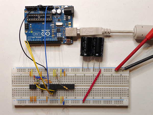 This picture shows my setup with RTC and external EEPROM. On the breadboard from left to right: 24AA256 EEPROM, DS1337 RTC and the ATmega328P. Above the EEPROM and the RTC is the RC network that conditions the pulses from the RTC (see here). The two resistors near the ATmega328P form the voltage divider to measure VCC. The orange wires from the controller to the RTC and the blue wires from there to the EEPROM give the I2C bus. I omitted the pullup resistors as the Wire.h library uses the internal pullup resistors of the controller.
Conclusion
The conclusion is: although we have one more chip we have reduced total enery consumption. The second point is that we have a bigger memory for storing our data. The real consumption of energy cannot be calculated only with the figures from the datasheets of the devices. Looking at the supply current with a scope gives in-depth information of what is really happening in the system. This enables us to directly compare different system configurations both in hardware and in software. The external 24AA256 is faster and consumes less power than the internal EEPROM.
The next post will show how to reduce energy consumption furthermore by using the page mode feature of the 24AA256.
Enjoy
heliosoph