
 Let’s take a capacitor as the power source for an arduino. But what sense does that make? This is totally nonsense you might say. A capacitor can’t store enough energy to run a microcontroller for a considerable time. Take a rechargeable battery to get it running. You’re right (at first sight).
But let’s have a closer look at this. The idea behind is: How long can a microcontroller like e. g. the ATmega328 run off of a capacitor when power consumption is reduced to the limit? When we get reasonable results we could make a Minimal Solar Arduino with a capacitor to store the energy. This is the idea behind this project: Building a solar powered arduino system with minimal power consumption and a minimum of components. The project is inspired by these great articles: Power saving techniques for microprocessors from Nick Gammon and Operating an Arduino for a Year from Batteries from Alan Mitchell. Thank you both for your work!
Capacitor basics
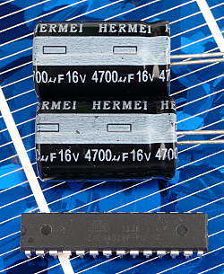
A capacitor stores electrical energy but the amount of energy is rather poor compared to a rechargeable battery. When you have a capacitor with 10.000µF (which is already rather big) you have: 10.000µF = 0.01F = 0.01As/V. This means: When you draw a current of 0.01A for 1s the voltage drops 1V. E. g. you have a capacitor charged to the voltage of 5V. Now you draw a constant current of 10mA out of the capacitor. After one second the voltage is only 4V.
When the capacitor is charged the voltage rises (and it falls when discharged, accordingly). (Almost) everybody knows that.
And you say: This guy is totally crazy! A mikrocontroller cannot run off of that! It needs a constant voltage of e. g. 5V and I don’t want to run my controller only for one second!!
I say: Yes, I understand you 😉 Now let’s have a closer look:
Power for an ATmega
In Nick Gammon’s article you can find (among others) two very important facts about powering an ATmega chip like the 328 used on the arduino Uno board:
- Don’t use the arduino board when you want to reduce power consumption as much as possible. The board with controller consumes about 46.6mA when connected directly to 5V omitting the voltage regulator on the board. When powered with 9V it consumes even about 55mA due to the voltage regulator. My own measurements showed the same.
The standalone ATmega328 uses about 15mA in normal operation and much less while asleep. - The supply voltage VCC doesn’t have to be +5V. The ATmega328 can operate from a maximum of 5.5V down to 1.8V when configured correctly. This makes it possible to have a varying supply voltage as we get it from a capacitor. With lower voltage the supply current is even lower which will also reduce power consumption.
Getting started
The project started with a fresh ATmega328P-PU. This is the chip of the Uno R3 board. Pay attention to have the 328P-PU but not the 328-PU: look here. The 328P-PU gives us the lowest power consumption possible and we don’t have to change files in the arduino IDE.
Take the right bootloader
Starting with fresh chip means that it doesn’t yet have a bootloader. There are several reasons why I decided to start this way: First of all I wanted to start from scratch. The other point is: I couldn’t find out which bootloader is on the pre-burned chips. As my design has the “minimum components” approach I want to use the ATmega’s internal oscillator and don’t use an external quartz. With the standard bootloader for the Uno we need an external clock. 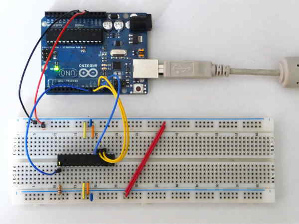
For a standalone ATmega using the internal clock there is a good tutorial on the arduino homepage: ArduinoToBreadboard. Althogh they say it doesn’t work with an Uno board I didn’t have any problems with my Uno R3 (when I did exactly (!) what is described in the tutorial) and got the bootloader onto the chip. The picture above shows the scenery for burning the bootloader. A fresh ATmega328 is pre-configured by the manufacturer to run on the internal clock source. If you want to check that burning the bootloader was successful you can take Nick Gammon’s Board Detector. When you read out the memory of the chip before and after burning the bootloader you see the difference.
Uploading your sketch
As I already had the Uno R3 board I decided to use it for uploading my sketches to the standalone ATmega. This is also shown in the ArduinoToBreadboard tutorial (bottom of the page, the right picture). The controller from the board is removed and only the USB-to-serial FTDI interface on the board is used. Remember to select “ATmega328 on a breadboard (8MHz internal clock)” in Tools–>Board of the arduino IDE. Now you can use the arduino IDE for your sketches and upload them as always.
Measuring uptime
What I want to do is: Charge a capacitor to 5V and see how long the ATmega runs until the supply voltage is too low. During this time the controller should measure VCC and store the values. After powering again with 5V read out the data and look what happened. This can be done with different configurations (especially using sleep modes) to see how long we can get…
So I set up the following:
- The controller measures VCC with an analog input. As VCC is not constant the reference voltage of the AD converter must be the internal 1.1V. So a voltage divider is needed that divides VCC by a factor of 5.
- The data is stored in the internal EEPROM. This way data is retained after power-down.
- VCC is measured repeatedly. During wait time different power-saving modes can be selected. This is similar to many data-collection applications for environmental data like e. g. temperature.
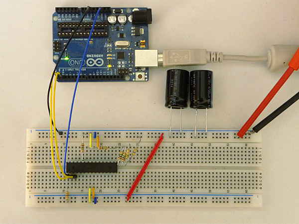 The picture above shows the initial setup. I take two capacitors with 4,700µF in parallel giving a total capacity of 9,400µF. The breadboard is powered by an external 5V source. The blue and yellow wires connect to the Uno board without controller to upload the sketch and read data afterwords.
When starting the measurement sketch the controller reads VCC in constant intervals and writes the data to EEPROM. After starting the sketch I disconnect all wires to the arduino board. This avoids uncontrolled current to and from the standalone ATmega. Also high logic levels from the arduino board that are higher than the supply voltage of the standalone ATmega can’t destroy the chip.
After that I disconnect the external 5V source. Then the chip runs solely from the capacitors and stops when the supply voltage is too low. After connecting 5V and the wires to the Uno board again data can be read from EEPROM.
The next post will show the first results with different configurations.
Enjoy
heliosoph
Hi Can u Teach me basic funda of bootloader other things in microcontroller.
Hello again,
the bootloader is the first piece of code that is loaded into the flash ROM of a new ATmega chip. This makes further programming (loading the sketch you want to run) possible when the chip is on a arduino board. Do some search on this topic on the web or in the arduino forum.
regards
heliosoph
Hi there, great writing.
I am pretty noob in electronic, and i dont understand what we see and what look like 2 little blue jumpers that connect + and – lines.
It can’t be what it look like, or i can’t understand why it doesn’t make a short cut.
Regards.
Hello Jengal,
thanks for your reply. The little blue things are (ceramic) capacitors. They block noise on the power supply. They sort of short cut high frequencies but they don’t affect DC.
heliosoph
Thanks a lot, I had great time reading all your site.
Did you managed tou get your atmega work with solar cell and capacitor ? Did you find an goal to this ?
I want to try to make a atmega (or attiny) work with a solar cell and a supercap.
But I wish I can add RF433 transmitter. Not sure if I will have enought power to make it works.
I was wondering another thing, not sure if you’ll be able to answer this. Is it possible to charge 2 capacitor in parallel (lets say my solar cell is a 2.5v and my capacitors too) and to use them as power supply in serial (in the same time), cause my atmega need 5v.
(as I said I am noob, maybe it s really easy, maybe it ‘s totally impossible, be kind :p )
Thanks again for you time and explanations
Your article inspired me to do more work on low power with regard to solar panels. See the end results at Solar powered Arduino.
Thanks for getting me back onto it!
– Nick
Seems like we’re inspiring each other 🙂
Your writings about minimizing power consumption of a ATmega328 actually were the base for my posts concerning the 328 and a supercap. When I wrote them my goal was to make a minimalistic low power pv system driving a 328 and some additional parts. But I stopped because I didn’t have a practical use for it and also because I had some private changes (e. g. moved two times). But there is a new idea around in my brain and it seems like now it’s the right time to bring it into reality.
So what I say to you is: Thanks for getting me back onto it!
heliosoph
Some genuinely good posts on this website , thanks for contribution.
Hi,
I’d like to thank you for the inspiration, I am designing a sensor network, until now I managed 7µA but poor timing sync (+/- 15 sec depending on temperature) using WDT.
I once considered using an RTC but I assumed the power consuption was too high to be worth it.
Anyway reading your blog I gave it a try h and I am now down to 4µA (Good enough to me as most of the current is now used in the transmit cycle) and much better timing (error < 1sec ).
I took a different approach and used the "alarm" functionnality of the DS1337. Basicaly I set the time to 00:00:00 and alarm to 00:15:00 and go to sleep waiting for an interrupt trigerred by the DS1337.
thanks again
JB
Thanks for the nice articles, this is really inspiring! I’m learning a lot from your articles and those from Nick Gammon. This also motivated me to start experimenting with a solar panel & super caps powered 3.3V breadboard Atmega328P as basis for a remote IoT node that can communicate sensor data via the LoraWan network in our country. My learning curve is steep but fun. 😉
I’m referencing your website, in case you want to check or look, the URL is https://hackaday.io/project/19884-solar-supercap-charged-iot-device.
Best regards,
Peter
Thanks for sharing this! I tried to replicate your experiments but I am struggling to do so because the images are low resolution and cannot read the resistors. Can you please help? What resistors did you use to get the AREF voltage to 1.1V ? Also, shouldn’t the analogReference been set to EXTERNAL according to the Arduino documentation?
Dear Mauro,
thank you for your comment and sorry for my late reply. You are right with my not-so-complete documentation and the picture that is not very clear. The voltage divider is high-ohm to have only very little power consumption. The voltage divider is built like this: 1M from AnalogIn0 to GND. 1M+1M+1M+470k+470k from AnalogIn0 to Vcc. As a 4M resistor isn’t available in the standard values I took some 1M in series. I decreased the value a little by changing one 1M to two 470k to use the full range of the ADC (not really necessary).
Vref must be the internal 1.1V (!) Vcc as reference isn’t possible as it is also the voltage I want to measure. If I would do so I would always get the same reading.
I hope this helps
heliosoph
Many thanks for your detailed answer! I was able to replicate the experiment with the right resistors and analog reference set up correctly.