 This is the second post about powering an arduino from a capacitor. The basic setup is described in the introduction. It’s an ATmega328P in a standalone setup with use of the internal clock source. The power comes from the two capacitors on the picture. The microcontroller measures it’s own supply voltage repeatedly in intervals and writes data to the onboard EEPROM. After starting the measurement the power supply is plugged out and the ATmega runs off of the capacitors until the voltage is too low.
In this post I will describe how long the setup can run with different power-reducing techniques.
The first test
For a first test the arduino was programmed in standard configuration. This means that no power-reducing steps were made. The intervals between the measurements are made with the delay() command. So the controller is fully operating the whole time. This is the code:
#include <EEPROM.h>

// the measured voltage
unsigned int voltage;

// The analog input where the voltage is measured:
int voltagepin = 0;

int addr = 0; // EEPROM address to write to

void setup() {
  analogReference(INTERNAL);
}

void loop() {
  while(addr < 1024) {
    voltage = analogRead(voltagepin);
    // write data to EEPROM
    // Lowbyte first
    EEPROM.write(addr, voltage % 256);
    addr++;
    EEPROM.write(addr, voltage / 256);
    addr++;
    delay(50);
  }
}
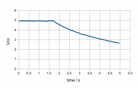
 The diagram shows what is happening. VCC was measured every 50ms. You see some noise on the curve. This is probably due to the ‘quick and dirty’ voltage divider with some resistors I had lying around. The controller was connected to the power supply at start. After 1.7 seconds power was plugged out. Then the ATmega ran on the capacitors for a little more than 3 seconds until the internal Brown-Out Detection shutted it off at 2.7V. The uptime of 3 seconds is what I expected and really isn’t a lot 😉
In the next steps I will add different power-saving methods like sleep and some other things to look how long we can go:
Step 1: First sleep mode test
In the first step the measurement interval is set to 1 second and the timing is done by the internal timer. So the controller can do the measuring and then sleep until the next measurement. To load the sleep library and to activate the timer the following lines are added at the beginning of the sketch:
#include <avr/sleep.h>
#include <avr/wdt.h>

// watchdog interrupt
ISR (WDT_vect) {
  wdt_disable();  // disable watchdog
}  // end of WDT_vect
The delay() command is replaced by:
  // clear various "reset" flags
  MCUSR = 0;
  // allow changes, disable reset
  WDTCSR = _BV (WDCE) | _BV (WDE);
  // set interrupt mode and an interval
  WDTCSR = _BV (WDIE) | _BV (WDP2) | _BV (WDP1);    // set WDIE, and 1 second delay
  wdt_reset();  // pat the dog

  set_sleep_mode (SLEEP_MODE_PWR_DOWN);
  sleep_enable();

  sleep_cpu ();

  // cancel sleep as a precaution
  sleep_disable();
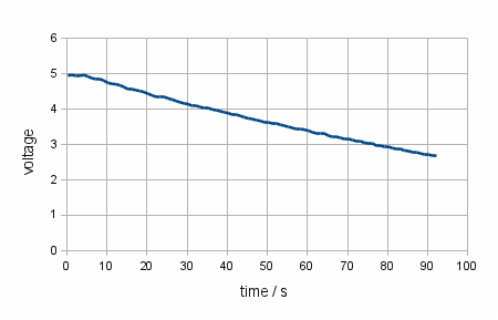
This code is copied directly from Nick Gammon’s page. The timer is set to 1s and then SLEEP_MODE_PWR_DOWN is activated. The controller stops after the sleep_cpu() command. When the timer finishes his interval the sketch continues at the same place.  We see that the standalone uptime has increased to 88s which is a lot compared to running the controller continuously. As in the first test the controller stops at 2.7V by the brown-out detection.
The sleep library makes putting the controller to the different sleep modes comfortable. Here you can find the documentation of the sleep library: http://www.nongnu.org/avr-libc/user-manual/group__avr__sleep.html.
Step 2: How low can we go
Disabling Brown-out detection lets the ATmega run with much lower voltage than before. This will give us an increase in uptime because the capacitors can be discharged deeper and so give more energy into the system. Brown-out detection is often disabled in software. I tried the same but failed. The datasheet of the ATmega328P told me why in chapter 9.2 page 40: “Upon wake-up from sleep, BOD is automatically enabled again.” This is the reason why the controller doesn’t start after wake-up. Brown-out detection can also be disabled permanently by setting the appropriate fuse:
avrdude -P /dev/ttyACM0 -b 19200 -c avrisp -p m328p -U efuse:w:0x07:m
This is the command-line for my Linux computer. For more info about using a Uno board for setting fuses look here.
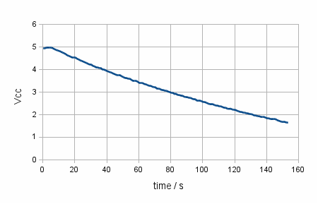
 After setting the fuse the controller also works at lower voltage. The image shows the result. The ATmega works down to a voltage of 1.7V. Now we reach a uptime of 147s. This is an increase of 67% compared to step 1. Reading the datasheet 1.7V is lower than the minimum voltage the ATmega is able to run with. One reason for this could be that measuring of VCC isn’t correct at this voltage level or that the controller can work at lower voltage than specified.
These first tests show that the total uptime of the system can be much longer than expected at a first glance. With some further tweaking it is possible to get even further. The next post shows the possibilities of power reduction both in the controller’s run mode and sleep mode.
Enjoy
heliosoph

Hi i learnt something from u ,thanks for that. good keep going,Can u help me .
I waana make dotmatrix panel with multi languages displayed in one.
panel,so iam confused how to develop easiest code for multilangauge display.Any application if u suggest which can be interface with rs232 hardware tell me. mail me if u have.
Hello,
look in the arduino forum http://forum.arduino.cc There you can find lots of information. Also look at the arduino playground: interfacing with hardware: http://http://playground.arduino.cc//Main/InterfacingWithHardware This also gives you a lot of useful info.
regards
heliosoph
Hi ,
1st – thank you for sharing – very interesting .
from carefully reading your post I think that you did not compare “apples to apples” when you did measurements before and after applying power saving Technics.
I think (maybe i’m wrong ) that writing to the EEPROM is an operation is a major power consumer .
before applying “power saving ” you wrote to the EEPROM twice every 50mS !! that means 20 times per second !!
While in your 2nd and 3rd example you wrote to the EEPROM just once per second ! (I assume that you can not write during sleep )
So – How do you know if the improvement was because the power saving technics or because you reduced the writing to the EEPROM by X20 ??
Amir
Thanks for your reply.
You are right: In my first improvement step I did two steps at once: Increasing the write interval and setting the controller to sleep whilst idle. First I should have set the controller to sleep mode and then, in the next step reduce writing data from 20 times per second to once per second. Then the power consumption of writing to the EEPROM would have been obvious. Writing to the EEPROM consumes quite some energy due to the long write cycle time. During this period of time the controller cannot go to sleep mode.
Best regards
heliosoph
Many thanks for sharing this fascinating research 🙂
I am experimenting with an ATMega328PU and it was seeming to remember what it was doing before the power was disconnected and restored. Remembering EEPROM and Flash is expected, but preserving registers and SRAM with the power off, even over night, that’s seriously freakish! Luckily (!) you confirmed what I suspected…
My AVR Assembler has an eco-friendly SLEEP [idle] command [equivalent to sleep_enable()] in the main loop and, the AVR’s BOD fuses are set to off. Wakeup action is taken by a Timer interrupt driven ISR. However, with the power off, it seems the smoothing capacitor on the breadboard’s power supply is able to drip feed the 328 with enough current to keep it alive in sleep mode. This was measured at an almost immeasurable 7uA. By shorting the capacitor, the processor shuts down, correctly.
Even this diminutive 470uF-16V capacitor on the PSU is enough to keep the 328 running silently for hours. Conventional wisdom says the LEDs die from voltage starvation in milliseconds because they drain the supply capacitors. But once the LED’s fall below their forward voltage ( > 1.8V ) the supply capacitors retain enough charge to sustain a snoozing AVR/Arduino.
I guess then the moral of the story is, the machines may be switched off, but are they really *OFF*?
Thanks for sharing.
Andy Beez
Thank you very much for your reply 🙂
Your approach is very interesting as you didn’t expect the results you got. To confirm this you can short the capacitor as you did or you can measure supply voltage of the AVR before you switch it on again. The question about are the machines really off is a bit philosophical because they unexpectedly keep data but they are not able to do anything: When they would return to operational mode then supply voltage would break down immediately as shown in my first example. So they are sort of ‘freezed’…
Very best regards
heliosoph