
 Now let’s put this all together. First we take the old setup from the first tests and set all digital I/Os to output and low and connect the analog inputs to GND. Surprisingly this doesn’t make a longer uptime. So obviously most of the electricity is consumed while sleeping. Let’s do some calculation:
Reading the analog signal and writing to EEPROM once takes 3.85ms (measured). Current is about 7mA. We consume 27µAs (time x current). During sleep as in our last configuration (ADC on, BOD off) we have a sleep current of 122µA and 1s of time for one period. So consumption during sleep is 122µAs! So most of the electricity is wasted during sleep according to the relatively high current and the much longer time.
Time for minimizing sleep current: Shut down ADC!
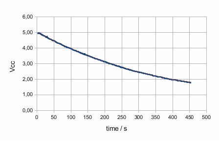 This is what we get 🙂 Analog-Digital-Converter and Brown-out Detection shut down whilst asleep gives us a total uptime of 450 seconds! This is around 150x longer than at the beginning (without sleep).
Brown-out Detection is enabled during run-mode. This stops the system at 1.8V. Without BOD we could get even lower but operation isn’t safe anymore.
The voltage divider that is used to measure VCC is connected to a digital output. During the measurement this output is set to HIGH. Before sleep it is set to LOW. When you draw only very little current from a digital output set to HIGH the voltage equals VCC. So now we don’t have any current through the divider while sleeping.
Here is a code example:
#include <avr/sleep.h>
#include <avr/wdt.h>
#include <EEPROM.h>

// Variables declarations:
// EEPROM address
int addr = 0;
// the measured voltage as integer
unsigned int voltage;
// keep the state of register ADCSRA
byte keep_ADCSRA;

// Pin declarations:
// The pin that supplies the voltage divider:
int dividerpin = 8;
// The analog input where the voltage is measured:
int voltagepin = 0;

// watchdog interrupt
ISR (WDT_vect) {
  wdt_disable();  // disable watchdog
}  // end of WDT_vect

void setup() {
  // set digital pins for low power consumption
  for (int i = 0; i < 14; i++) {
    pinMode(i, OUTPUT);
    digitalWrite(i, LOW);
  }
  // set analog reference voltage
  analogReference(INTERNAL);
}

void loop() {
  while(addr < 1024) {
    voltage = analogRead(voltagepin);
    // write data to EEPROM
    // Lowbyte first
    EEPROM.write(addr, voltage % 256);
    addr++;
    EEPROM.write(addr, voltage / 256);
    addr++;
    // shut down ADC
    keep_ADCSRA = ADCSRA;
    ADCSRA = 0;

    // Go to sleep for 1 second (with code from Nick Gammon)
    // clear various "reset" flags
    MCUSR = 0;
    // allow changes, disable reset
    WDTCSR = _BV (WDCE) | _BV (WDE);
    // set interrupt mode and an interval
    WDTCSR = _BV (WDIE) | _BV (WDP2) | _BV (WDP1);    // set WDIE, and 1 second delay
    wdt_reset();  // pat the dog
    digitalWrite(dividerpin, LOW);

    set_sleep_mode (SLEEP_MODE_PWR_DOWN);
    sleep_enable();

    // turn off brown-out enable in software
    MCUCR = _BV (BODS) | _BV (BODSE);  // turn on brown-out enable select
    MCUCR = _BV (BODS);        // this must be done within 4 clock cycles of above
    sleep_cpu();

    // continues here after wakeup
    // cancel sleep as a precaution
    sleep_disable();
    ADCSRA = keep_ADCSRA;
    digitalWrite(dividerpin, HIGH);
  }
}
The while-loop prevents overwriting the first bytes of the EEPROM when more than 512 measurements can be done until power is down. The variable keep_ADCSRA saves the state of the ADC status register during sleep. After wakeup the variable is written back to the register to have the ADC in the same state as before. The voltage divider is connected to dividerpin and turned off during sleep.
Let’s have a look at what is still powered during sleep: The watchdog timer is needed in this setup to wake up the controller. Supply current is 6µA with the watchdog enabled. If we want to get rid of it wakeup has to be done via external interrupt by e. g. a RTC like the DS1337. This is what is done in the next post.
Another topic to talk about is how long can we go with the capacitors:
Self-discharge of the capacitors 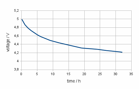
Regarding the capacitors, self-discharge can have an impact on the maximum possible uptime. As I couldn’t find anything in the datasheet I decided to measure it. After charging one of the capacitors to 5V I disconnected it. Then I measured the voltage once an hour. Therefore I connected the capacitor to the voltmeter only for the duration of the measurement and then disconnected it again to prevent additional discharge due to the resistance of the voltmeter. The result was better than I expected: The capacitor lost 0.7V in 24 hours.
So this will give us enough time 🙂
In the next post we will add a RTC to have a more exact and more flexible system timing and to bring
Enjoy
heliosoph
Dude You are a F###$#$% STAR in my eyes I have been looking for this info for months, I am in the process of developing a ultra low power device and i need to run the device of a single 55mah battery for one year. if you are interested I will be more then happy to see your input into my system and ideas +A!
Thanks for your reply! It’s nice to see that some others can do useful jobs with what I wrote. The basic idea of my tests was to have a small amount of energy (capacitor) to keep total uptime short. So it is possible to compare different configurations without having to wait (almost) eternally. For very long operation times also look at the self-discharge rate of your battery.
heliosoph
I will look into it, what i am currently doing is designing a UNO shield with a separate 328p on it with three different hardware (power sourcing) option and the uno just monitors the power used from the device. this way I can program the UNO as a monitor and still be able to run the other MCU on its own power source.
Hi Heliosoph
I felt inspired by your blogs to do more testing on this subject and I designed a Arduino shield to test the Arduino sleep library more in depth. you can see the board here http://powerduino.blogspot.com/ what it consist of is a standalone Atmega 328p with 4mhz clock and a very accurate current measuring IC. you can power the shield from either the UNO it self or from an external source (like caps).
anyway would like to get your comments on this to see if i missed something.
Congratulations to your blog, looks great!!
I would suggest to take a bigger solar cell and then have the system totally powered by solar energy. When you have low light conditions in your application (= indoor use) think about using amorphous silicon cells for better energy yield.
best regards
heliosoph
Very interesting series of posts. I’m testing this low power board https://talk2.wisen.com.au/product-talk2-whisper-node-avr/ to run of a cr2032 and already used a few of your ideas. I personally can’t use a capacitor as I need to power one or two sensors which only run down to 2.7V
Thanks for your reply!
The idea about the capacitor was to have a really minimalistic system. You can always increase it to your needs. Any battery contains much more energy than a capacitor. The idea about the capacitors was also to have a testbed with a short runtime and then change to a supercapacitor and charge it from photovoltaic cells (this post will hopefully come soon).
Regards
heliosoph