
 In my project “Arduino powered by a capacitor” (start, first tests, reducing consumption, optimized tests) I want to use an extermal timer like the DS1337 to generate periodic interrupts for my ATmega328P that will wake it up from sleep to do datalogging or whatever is the desire.
Using a real time clock (RTC) has the advantage of higher timing accuracy but also brings in a new problem that is described and solved in this post.
ATmega328P external interrupts
The RTC gives us the signal for the external interrupt that wakes up the controller. While in sleep mode we use SLEEP_MODE_PWR_DOWN to have the lowest possible supply current. But this also brings us a restriction (see ATmega328 datasheet on pages 39/40 and 71): Other than in active mode the external interrupt pins can only detect a LOW level but not a rising or falling edge. This means that a interrupt is triggered whenever the signal is LOW, e. g. directly after the interrupt is detected.
The interrupt wakes up the controller. Then the interrupt handling is started. In my example code (see below) there is a very short Interrupt Service Routine (ISR) and then interrupt handling is done in the main loop(). The first thing we have to do in the ISR is to disable further interrupts to prevent multiple interrupts being created as our signal on the interrupt line will stay LOW for some time. Now the controller does it’s job and then goes to sleep again. Before sleeping interrupts must be re-enabled. Otherwise the controller will never wake up again. At this point it is important to understand that when the signal that triggered the interrupt is still present at the time interrupts are re-enabled another interrupt is fired immediately. This can be prevented only by keeping the duration of the LOW signal shorter than the operating time of the controller during the ISR’s job.
What it boils down to is: The external interrupt signal must be long enough to be detected by the sleeping controller and shorter than the time duration of the Interrupt Service Routine. When the signal is too short no interrupt is detected. When too long more than one interrupt is created by one single pulse on the interrupt line.
RTC as interrupt source
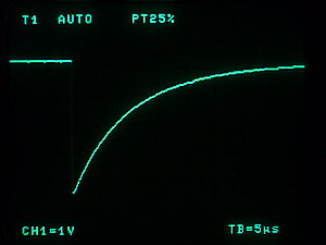
Now let’s go back to our RTC: We will use the square wave output of the RTC with a frequency on 1Hz generating an interrupt once a second. When we look at the RTC we see the square wave signal with a duty cycle of 50% as it is created by simple frequency division. This means that the signal is 500ms HIGH and then 500ms LOW. So the problem mentioned above will arise because the ISR takes much less than 500ms in most cases. We don’t need a very long LOW signal but a short one that only triggers the interrupt and then goes HIGH again.
Interrupt signal conditioning
 One possibility to limit pulse duration is with a capacitor and two resistors as shown on the left. The output of the RTC is open drain (like open collector if it were a bipolar transistor output). Normally the signal is generated with a pullup resistor giving a pulse time of 500ms (on-time of the FET). With R1 and C1 we get a different behaviour: Assuming that C1 is discharged when Q1 switches on the output voltage drops to approx. 0V and then rises again because C1 is charged via R1. The voltage rise happens with the time constant t = R1 * C1. This determines the duration of the interrupt pulse. Output voltage stays high and after 500ms Q1 goes to off state. Then C is discharged via R2. R2 can be much bigger than R1 because discharge time can be much longer than t. A high value for R2 ensures that the output voltage really rises almost up to Vcc and minimizes additional loss by the current through R1 + R2 during on-time of Q1.
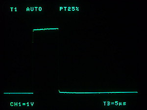
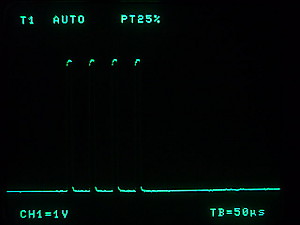
 Tests have shown that C1 should not be smaller than 4.7nF to have the output voltage really go to LOW level. On the left you can see the pulse that triggers the interrupt. The values for R1 and C1 are 2.2kΩ and 4.7nF. With a variation of R1 the pulse duration becomes shorter or longer. R1 can be as low as 220Ω giving a very short pulse and an interrupt is still created.
Example sketch
For the tests I wrote a simple sketch with interrupt handling. The ATmega328P running at internal 8MHz clock is in sleep mode most of the time. The controller wakes up once a second by external interrupt 0 fired by a DS1337. Then it does a very short job (put a digital output to HIGH and then to LOW) and goes to sleep again. With the very short interrupt handling time problems with multiple interrupt triggering as described above can be observed easily. The interrupt part of the code is copied from Nick Gammon’s page on saving power and the RTC initialization is taken from John Vaughters’ page. Thank you both! The same can be done with the very well-known DS1307 that also has a square wave output. Then set the register address to 0x07 (07 hexadecimal) and the data byte to 0x10.
#include <Wire.h>
#include <avr/sleep.h>

// I2C bus address declarations:
#define DS1337_I2C_ADDRESS 0x68  // DS1337

void wake ()
{
  // cancel sleep as a precaution
  sleep_disable();
  // must do this as the pin will probably stay low for a while
  detachInterrupt (0);
}

void setup() {
  // initialize ouptut pins
  pinMode(7, OUTPUT);

  // initialize I2C bus
  Wire.begin();

  // initialize RTC
  Wire.beginTransmission(DS1337_I2C_ADDRESS);  // Open I2C line in write mode
  Wire.write((byte)0x0E);                      // Set the register pointer
  Wire.write((byte)0x00);                      // Set the status register
  Wire.endTransmission();                      // End write mode
}

void loop() {
  digitalWrite(7, HIGH);
  digitalWrite(7, LOW);
  set_sleep_mode (SLEEP_MODE_PWR_DOWN);
  sleep_enable();

  // Do not interrupt before we go to sleep, or the
  // ISR will detach interrupts and we won't wake.
  noInterrupts ();

  // will be called when pin D2 goes low
  attachInterrupt (0, wake, LOW);

  interrupts();
  sleep_cpu();
}
 Watching digital pin 7 with a scope shows us the beaviour: The output goes to HIGH and then to LOW again. This happens only once. We see that now additional interrupts are triggered because the loop() is run only once (and then again once at the next interrupt pulse).
 Increasing the value of R1 makes the interrupt pulse longer. With a value of 47kΩ the pulse is long enough to generate three additional runs of loop(). A value of 15kΩ lets the loop run twice and values of 10kΩ or below give only one output pulse as desired.
Conclusion
Conditioning of signals that shall trigger external interrupts is necessary to prevent multiple triggering from one single pulse. This can be done with a RC network as shown above. C1 should not be smaller than 4.7nF to have a good LOW signal. R1 can vary from 220Ω to 10kΩ to produce one single interrupt with the given short interrupt handling. A value of 2.2kΩ is chosen that should fit for most cases. Then only one interrupt is generated no matter how long the original signal will last after the interrupt is started.
Enjoy
heliosoph
How I connect the arduino and RTC module??
Hello Angel,
with the DS1337 you have two options: You can take the square wave output as described in to post. Or you can take one of the alarm outputs and use it as an interrupt. Then you will have to clear the alarm in the RTC after the interrupt service routine.
heliosoph
Hello thanks for your information . Does a microcontroller consume zero power while in sleep mode ? or what i did not understand
Hello prasant,
when in sleep mode a microcontroller still consumes power. But you can have the ATmega328P consume below 1uA. You can read more in my article about reducing power consumption.
Best regards
heliosoph
Hi Heliosoph,
Im just wondering is there anyway to set up the device working for only couple hours a day -> go to sleep -> wake up in next 7 days -> repeat all the steps.
I try to use DS3231 to do it but just got to the part where I can wake up the device at only specific time. Not automatically keep wake up in next 7 days.
Cheers.