
 In this post we will add a second photointerrupter to our rotary encoder. This will give you information about the direction your rotary device turns. So you will be able to count forward and backword depending on the turning direction. This is necessary e. g. for many positioning application. The encoder we will make is also called a quadrature encoder.
How it works
 We name the two photointerrupters A and B. The pulses are created the same way as with the simple rotary encoder from the last post. The picture shows the signal you want to get from your encoder. There is a phase shift of 90° between signal A and signal B. When you connect one of the signals to your counter you will have the simple rotary encoder again.
Now let’s have a closer look to how a counter works. It doesn’t count (=increase it’s value) when the signal is HIGH or LOW but at the moment the signal transits from one state to the other. The transition from LOW to HIGH is called the rising edge of the pulse, the transition from HIGH to LOW is called falling edge. Your counter counts either on the rising edge or the falling edge depending on how you initialize it. In this example it counts on the rising edge. We connect one of the signals to the counter, e. g. signal A. This gives us the pulses we count. The picture above shows that every time signal A has it’s rising edge (the moment the counter does it’s job) signal B is LOW.
 The second picture shows the same rotary encoder but turning in the opposite direction. Now the phase shift between signal A and B is -90°. The counter input is still connected to signal A and it counts on rising edge of the signal. The picture shows that signal B is HIGH when signal A rises.
This is how it works: Take one of the signals A or B to give you the pulses you want to count. The other signal tells you the turnung direction. In the moment the counter has to change it’s value the signal is HIGH or LOW only depending on the direction of turn. This can tell the counter to count forward or backward.
How to build it
This is a upgrade of what we did with the simple rotary encoder. We take the same index disc but add a second photointerrupter.
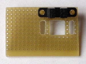
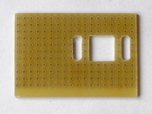 We have to find a way to align both photointerrupters and adjust them to get the right phase shift. With photointerrupters that have mounting holes like the TCST 2103 you can easily do this on a piece of perfboard. Prepare it as shown on the picture. The holes are for the photointerrupter that can be adjusted. Saw or mill two long holes for the screws and a bigger one for the connectors.
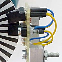
One photointerrupter is fixed and will simply be soldered on the board. When soldering it you can tilt it to have it „look“ to the center of the index disc. This will give you a better signal.
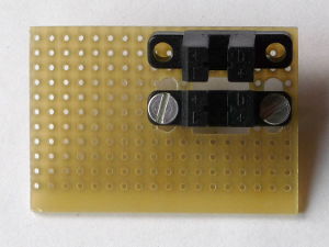
Fix the second one with two screws in the long holes. Now the screws can slide in the holes and the connections are done with wires. You can adjust the photointerrupter by simply moving it up and down.
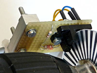
Bring the assembled board to your index disc and do the tests that are described in the photointerrupter details post. If you want to save energy connect both LEDs of the photointerrupters in series. Connect the outputs A and B to a scope and run your device. Having both signals on the screen you can bring the phase shift to 90° by moving the adjustable photointerrupter up and down in the long holes. When you don’t have a scope set the LED current to 20mA and connect two low power LEDs instead of the pullup resistors between OUT and Vcc. Turn your device slowly by hand and you will see the signals directly.
When everything is properly adjusted and fix you have your quadrature encoder ready. In the next post we will connect it to the arduino and look at the software. Furthermore there is an example of practical use: a winding machine.
Enjoy
heliosoph
Hi,
Thanks for your posting. I wasn’t sure how to do interrupts on the Arduino for my own quadrature encoder that I bought from China on eBay. They are slowly getting less expensive and I was able to buy a nice sealed ball bearing unit with 600 ppm (2400 codes per rev) for about $16 with shipping included.!
I think there is a flaw in the description and subsequent code that you post for the Arduino. I have no clue how it could be working as it defies logic to me.
The direction of the rotation of the disc shouldn’t cause the signal for channel B to invert suddenly relative to channel A. Your second diagram sort of implies that. The relationship should be fixed (B is either low or high whenever A transitions low). So it matters not whether you just moved right or left, at the transition point for that interrupt input is always going to find the adjacent channel at the same level. The only way this wouldn’t be true is if the disc is moving so fast that by the time the other channel is read the disc moved far enough to cause the other channel to change. That would likely be very fast.
So in reality you need to interrupt at each LEVEL change, not each RISING or FALLING of one of the channels. Then it is necessary to find out what the new level on the interrupt input is when that interrupt occurs, and then from that and also the level of the other channel it is possible to know which way the count has gone (up or down; + or -; right or left; clockwise or counterclockwise).
It’s a quadrature because there are four codes per cycle given that there are two channels. Their 90 degree separation makes it so that four codes are generated per cycle and multiple cycles per revolution of the disc.
I am not sure how it is that your QUADRATURE code would work at this page:
http://heliosoph.mit-links.info/rotary-encoder-software-for-arduino/
I think the code SIMPLE ENCODER code is probably ok but perhaps you didn’t actually test using the QUADRATURE code? Or perhaps I am missing something. I haven’t tried myself yet and we are all prone to make mistakes… but the description on this page and the code on that raised a red flag in my head so I thought I’d mention it.
Respectfully, -Paul D.
Hello Paul,
thank you for your reply. I thought again about what I wrote in this post. The good thing of arduino is: You can try things out with little effort. I had my quadrature encoder running with the code examples in my post and it was working as expected.
I try to explain to you what happens in the quadrature encoder: Suppose you have a index wheel with two tracks, an inner track and an outer one. The stripes on the outer track are moved a little bit clockwise to give a 90 degree phase shift between the two tracks. Now you have two light barriers that read one track each. They are mounted at the same angular position, one over each track. When you turn the wheel clockwise then the signal on the outer track always comes 90 degrees before the signal of the inner track. So far, so good. Then you turn the wheel counterclockwise. You will see that now the signal of the outer track comes after (!) the signal of the inner track. Try to imagine this right before your inner eye. When you got it then you will see that now you have a phaseshift of -90 degrees. This leads you to the two signal diagrams in my post. These are not geometrical but time diagrams. When you understood that point you will see that checking the level of signal B everytime signal A has a rising edge will tell you the direction of rotation. You can verify this with the encoder you have. It probably has open collector outputs. Connect a LED with resistor from +5V to each output. Then turn the encoder slowly by hand.
On the second point you are right: You can decode all edges of signal A (and reed the direction from signal B). Then you will get a higher resolution.
heliosoph
I get what you are saying. I had neglected to see that your timing diagrams had time as the X axis and not rotational position. My bad for not reading what you wrote carefully.
There are still some noteworthy flaws in doing it the way that you are. For instance, if the wheel is nearly motionless but just on the edge of generating the rising edge interrupt (ch. A), every time there is a vibration, causing transitions on this line, it will think the wheel turned four quadrature steps in a given direction. It will skip and skate as repeated rising ‘A’ edges will always see ‘B’ at the same level, assuming it doesn’t vibrate more than two quadrature steps. that will increment (or decrement) the “count” repeatedly on each one of those transitions.
Really, the only reliable way to do the the quadrature using a Arduino directly is by generating interrupts using both channels and on both the rising and falling edges. Usually a separate chip is used for this as many back to back interrupts might occur given a situation like what I described above (vibrational bouncing). That way the chip can just notify the processor, at a lower priority level, that there has been a change in count, and the processor can read the chip to find the new count value. If the processor is really busy, perhaps it will be flagged multiple times due to multiple updates in position but nothing will “slip”. In that way, the count should remain faithful.
Your method probably works fine for stuff that doesn’t care if the disc gets out of index, especially if the disc is to be in continuous motion. If you just want relative position change and don’t care about absolute rotational accuracy then it is fine. It all depends what you are trying to achieve.
By the way, I believe that there are encoders that produce sine waves instead of square waves from their wheels. That way the opto-detector level can be fed to a comparator that has hysteresis that will prevent some glitching when residing at the transition positions. Normally the square wave ones are adequate though.
-Paul
Hello Paul,
thanks again for your reply. Your point of positioning errors due to vibration or mechanical tolerances is a problem that can’t be solved with what I wrote. This is where the sine wave encoder come into action.
In my example I have a winding machine and I have 36 steps per turn on my encoder. In this application it’s absolutely no problem when I have some single steps more than I should. And by playing with it I learned about the positioning problem you described.
heliosoph
I found this which appears to be a really good explanation of reading quadrature encoders. The code may seem cryptic but it is this way on purpose. Interrupt routines need to use a few clock cycles to complete as possible.
http://makeatronics.blogspot.com/2013/02/efficiently-reading-quadrature-with.html
-Paul