
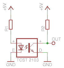
 In my second post about photointerrupters I show you how to get things working properly and how to spend only as much energy as necessary. The schematic diagram shows the basic wiring for a photointerrupter like the TCST 2103 that I introduced already in my first post. Now it is time to find the best values for the two resistors.
The suggested LED current is 20mA and the LED voltage is 1.1V. So when Vcc = 5V choose R1 = 180Ω and R2 = 2.2kΩ and you will get safe operation. The total current will be 22mA for your photointerrupter. What we will do here is to reduce current consumption for saving energy.
Reducing current
The maximum current the phototransistor in the output stage can drive depends on how much light comes from the LED. So my first idea was to reduce the current through R2 as much as possible and then reduce LED current so that the transistor still gets enough light. As the logic inputs of CMOS devices need only some μA I thought about reducing LED current accordingly and saving energy this way. Then I did some testing and it turned out that there was a problem with the switch off time of the transistor. Switch off time increases very much when the transistor current is low. When Vcc = 5V and R2 = 10kΩ the current is 460μA and the switch off time of the transistor is around 200μs. When you make the LED current as low as possible then switch on time of the phototransistor is in the same region. So your maximum pulse frequency is around 1kHz. You can get such frequencies easily from a rotary encoder. If you have a higher frequency R2 must be smaller to decrease switch on and off times. If you reduce the current more, e. g. 46μA with R2 = 100kΩ then swith off time is 1.5ms. Here R1 = 10kΩ is a good choice with Vcc = 5V. LED current is now 0.4mA. This is way below the suggested 20mA!
Personally I would not increase R2 to more than 100kΩ as you can get additional noise problems because of the high impedance of your circuit.
In your real application think about increasing LED current about 30% … 50% to be on the safe side. In reality you have different performance of individual photointerrupters even if they are the same type. And performance also changes with temperature and time.
Testing
To be sure about the resistors check it. With the LED off the output voltage must exceed 4V (3.6V minimum for arduino plus noise) when Vcc = 5V to be safely recognized as logical HIGH. When the voltage is too low decrease R2. When you turn on the LED output voltage must be around 0.4V. If it is higher decrease R1. When you have something in the gap that absorbs part of the light from the LED then do your testing with that in the gap. E. g. when you have made a index disc from acrylic and some black stripes on it then put it in the gap (the space between the stripes!!). You will have to increase LED current in order to compensate the absorption.
When you have fast signals, e. g. from a rotary encoder then do your testing with a scope to be sure that switch on and off times are short enough.
Ambient light
As photointerrupters are optical sensors they react on every light that falls onto the detector. This means that the phototransistor drives some current when exposed to daylight. Although the TCST 2103 has a daylight blocking filter the phototransistor reacts on ambient light. With daylight conditions in a room you get some 10 to some 100μA. When exposed to direct sunlight there can be more than 10mA!! Measuring this current is easy, just replace R2 by an amperemeter and don’t connect the LED. The real current varies a lot depending on momentary light conditions. Keep this in mind when you choose a place for the device. You can reduce ambient light too by choosing a photointerrupter with the minimum gap width that is possible in your application.
When you can’t get rid of ambient light then adjust the resistors accordingly. Test it. Be sure to have the maximum of ambient light that is possible in your situation. First decrease R2 to get a stable HIGH signal with LED off. Then find R1 in order to have your output voltage at 0.4V with LED on (=stable LOW signal).
More than one photointerrupter
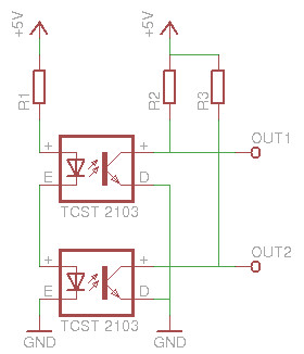 You can connect the LEDs in series as shown in the diagram. You will as much current as before but now for two LEDs. The forward voltage of the LED is 1.1V. Having two LEDs the voltage drop across R1 is 2.8V. E. g. your desired LED current is 1mA then R1 is:
R1 = U / I
R1 = 2.8V / 1mA = 2.8kΩ ==> 2.7kΩ
When you have three LEDs in series look at the variation von the supply voltage. When supply voltage varies +/- 5% then LED current will vary +/- 17% because of the low voltage drop on R1.
So with Vcc = 5V you can connect 2 LEDs in series without problem. When connecting 3 LEDs look at the minimal value of Vcc in your circuit. And wiring 4 LEDs in series doesn’t work because current variation due to Vcc is to high.
Now you are ready to make your own rotary encoder or quadrature encoder together with the code for your arduino.
Enjoy!
heliosoph
Thanks for this explanation. It’s very helpfull.
I have a TCST 2103 connected as you explained, using R1 = 180Ω and R2 = 1.5kΩ which gives me 0,12 V min and 5,3V max connected extern and measured with a multimeter.
But when I connect it to my arduino, my min and max values are 3.3V and 5.3V, so I’m not getting an interrupt. Any idea what goes wrong?
Regards
Hello,
how did you program your arduino pin? Input or output, pullup resistor on or off?
Regards
heliosoph
I have a question, is there a way to wire your circuit so the OUT signal is HIGH when the switch is not triggered? (the opposite it works now). and LOW when the switch is triggered.
Hi miro,
it depends on what you mean with ON and OFF. In the standard scheme as shown in the post the output is LOW when the transistor is ON. When light shines on the transistor it turns ON and the output is LOW. When the beam is interrupted the transistor turns OFF and the output goes HIGH.
I think what you mean is the opposite behaviour to what is given. You can interchange the transistor and the output resistor. Connect the collector of the transistor to +5V amd the emitter to your output pin. Then connect one end of the resistor also to the output pin and the other end to ground. As the transistor is a phototransistor you don’t have to worry about the voltage on the transistor’s base so this can easily be done.
Now when light shines on the transistor it turns ON as before and the output goes HIGH. When the beam is interrupted the transistor switches to OFF state and the output will be LOW because of the resistor.
It is important to know where your output pin will be connected to. With any CMOS-like input there will be no problem. With a good old standard TTL input it is possible that the resistor doesn’t sink enough current to keep the input low.
Hope this helps
heliosoph