
 These times it seems like everybody does his PCBs at home and posts about his process. So do I. I bought me a used face tanner in order to use it as UV lamp for my PCBs. There is also nothing new to what many others did before. The face tanner also had a time switch that (I thought) would make it a perfect UV lamp without the need of modifications. But the time steps were too coarse. So I modified it to have a finer time control. This is what this post is about.
The original unit
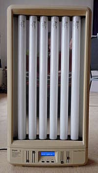
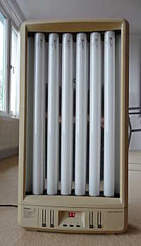 When the face tanner came to me I was surprised that it was much bigger than it looked on the photo. It has 6 tubes with 40W each giving a lighting area of 55cm x 30cm. Should be enough for my 3cm x 2.5cm PCBs I do at the moment 😉 With the integrated digital time switch one can adjust exposition time from 1 to 99 minutes in steps of one minute. I thought that this would be perfect for my application. During the first tests it turned out that the steps of one minute were too coarse because the lamp is very strong. Two minutes of exposition time were alredy too long. It was time to hack the device. I hoped to find some TTL logic and thought about altering the time base to have it run faster because I wanted a hack with little effort. But then, what a surprise: The design was more up-to-date than I expected. The picture below shows the original PCB.
 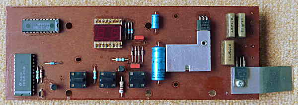 The time switch is made with a COP410L microcontroller and a MM5484 as display driver. The possible clock freqency range of the controller is rather small giving not enough space for acceleration without overclocking the chip. Ok, so time has come for a ATmega…
Replacing the board
I decided to build a new board with a ATmega328P (arduino Uno R3 chip) and to take a salvaged 16×2 LCD display. The ATmega328P runs on the internal 8MHz clock. This gives enough accuracy for my application and saves some components. Switching the lamp was originally done with a BT136 triac. This has the big disadvantage of a direct coupling between the controller and mains power. A solid state relay does the job now having the electronics insulated from mains. The original 9V transformer is reused to power the new unit. 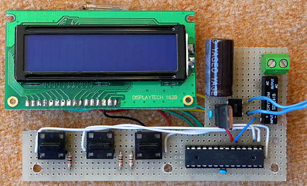 The picture above shows the new board with the new display. The two wires on the right side come from the original transformer. Power supply is completely standard with a B40C1000 (40V 1A) rectifier, a big electrolyte capacitor that I found on my desk and a 7805 with two 100nF ceramic capacitors producing stabilized 5V for the controller and the display. The display itself is a salvaged Displaytech 162B with led backlight. It had a shiny metal frame that I painted black. The display is HD44780 compatible as so many others. It is connected to the ATmega328P as described in the arduino LCD tutorial. The pinout of the 162B isn’t the same but the datasheet tells the pin names. The push-buttons were unsoldered from the original board. On the new board they are in the same positions to fit to the case again. The have pullup resistors and are connected to digital pins 8, 9 and 10 of the ATmega328P. The solid state relay is a Crydom SDV2415 capable of switching 1.5A. On the top of the board is the connector for the lamp. The three holes on the bottom of the board fit to the original fixing in the case.
 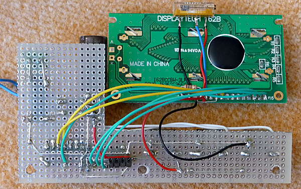 On the backside of the board and display. On the back of the display you can see the resistor for the backlight and the potentiometer for adjusting display contrast. The green wires are the data lines, the yellow wires are display control. Red and black are +5V and GND. The white wires go from the bush-buttons to the ATmega328P.
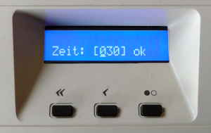
 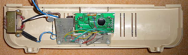 Here you see the new board in the original case. The transformer is where it ever was. The board is fixed with the original nuts and the display is glued in place with some acrylic.
Software stuff
The good thing about Arduino and related hardware is that there are many tutorials, libraries and code examples around. The LiquidCrystal library is already included in the standard Arduino IDE. As I connected the display to the ATmega328P according to the tutorial (see above) the library and examples work without changes. To have the push-button actions detected and transformed into display actions I selected the M2tklib. This library has a lot of support for building common things like menue structures, modifying numbers and a ok button. I simply took the U32 example and added some lines to count down the variable that is set by the buttons once a second and switch on and off the output pin. That’s all. At the moment only 2 of the 3 bush-buttons are used. The software stuff can be extended when wanted or necessary. For my application it works good and programming time was short. Thanks to the makers of the M2tklib and LiquidCrystal lib (and all the Arduino stuff, accordingly)!!!
Summary
 The goal of the project was to hack the face tanner having only little effort and to keep most of the hardware. As it is only one single device I took a perfboard as the base. The circuit on the new board is just standard, nothing special. Only very few components are needed. The solid state relay separates the control logic from mains power. The relay works in it’s maximum power range and becomes warm but not hot after some minutes. For me this is totally ok. If somebody wants to have long exposition times he should think about a bigger one. Modifying the case was easy with my proxxon handtool and a file. The new display fits perfectly to the case and looks even better than the original one (ok, my opinion, not surprising 😉 ). The software is merely a quick-and-dirty thing but works good. Now I can adjust UV exposition time for my photopositive coated PCBs the way I want. A first test showed that exposition time should be around 50 seconds. Yes, the lamp is really powerful!
Enjoy heliosoph
Pingback: Face Tanner PCB UV Lamp is So Bright, You Gotta Wear Shades - RaspberryPiBoards