
 In this post I will show you the basic use of a photointerrupter. The type in this example is a TCST 2103 from VISHAY. There are only two semiconductors included in one case and it is simple to use. But you have to know how…
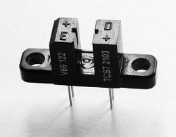
You can find the TCST 2103 datasheet here. This photointerrupter is very common and replaces the older CNY 37. It consists of a infrared LED which is called the emitter (E) and a phototransistor called the detector (D). Both devices are housed in the same package so no mechanical adjusting is needed. On the side of the transistor there is a daylight blocking filter to make the photointerrupter less sensitive to ambient light. You can solder it directly to a PCB or perfboard or you can use the two mounting holes to fix it anywhere you want to.
Different types
The two basic types are the transmissive one (gap type) as the TCST 2103 and the reflective. The transmissive type is much easier to use because all optical elements are already adjusted. A signal is generated by simply interrupting the light beam by an obstacle. The reflective type has the LED and phototransistor beneath each other and the light must be reflected by some sort of mirror. Proper position and alignment of the mirror is important to get it working properly. In most cases the transmissive type is easier to use e. g. when you want to count pulses to make a rotary encoder.
Most photointerrupters have an analog output as shown here in this post. This is good in most cases. If you have a very slow signal because the movement of your mechanics is very slow then take a device with a digital output. Then you also get defined pulses. An example would be the GP1A173 from Sharp Microelectronics which has a output stage with a schmitt trigger.
Photointerrupters vary also in the form of their case. Some of them have mounting holes as the TCST 2103 (see picture above), others don’t. The other important thing is the width of the gap. It must be large enough to let your moving part run freely. But the larger you make it the more problems will occur with ambient light. So choose the gap only as wide as necessary.
Connecting
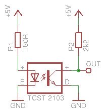 Here you see the standard wiring diagram for the TCST 2103 and many others. R1 limits the current of the LED to 20mA. The output is a open collector stage so a pullup resistor is needed. The output is LOW when the IR light of the diode shines on the phototransistor. So nothing is in the gap. When you put an obstacle into the gap the transistor goes in the off state and so the output goes HIGH. You can connect the output directly to a digital input of a microcontroller or other logic device as long as the transition from HIGH to LOW or LOW to HIGH is not too slow (see above).
Wiring is very easy because you find the description of the pins directly on top of the case as seen in the first picture.
Using
You can use the photointerrupter for controlling the position of a moving part (check if the part is in the desired position or not) or you can count pulses from a rotating index disc to measure the rpm of your motor (aka rotary encoder) or whatever you want.
In the next post you can find some information about choosing the right values of the resistors for spending less current and getting a good signal. After that It’s time to build a rotary encoder and then a quadrature encoder with forward / backward detection. Together with some code you will be able to run your application.
Enjoy!
heliosoph
Pingback: Tachometer | Pearltrees
Dead indited content material, Really enjoyed looking through.
Best for the topic..!!
Thanks for the flowers!
Regards
heliosoph