
In the first and second post of this series you saw the basics of how to use photointerrupters. Now it’s time for practice. We make a rotary encoder. Here we take a single photointerrupter that gives us the pulses we can count. In a later post we will take two of them to get information about the direction of rotation. But now let’s start with the simple version.
Index disc
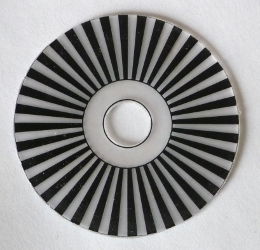 First of all we need to create pulses. Therefore we make an index disc. The details of it depend on how much space you have, how many pulses per turn you want, the photointerrupter you use and what machines you have to produce it. An easy way to make it is with a CD cover or any thin transparent acrylic, adhesive transparency sheet and a laser printer. Take a drawing software like Inkscape, LibreOffice Draw or whatever you want and draw your black stripes as seen in the picture. Print it all to the transparency sheet and fix it e. g. on the CD cover. Then saw it. Also saw the hole in the middle. Sawing is easier than drilling because when you try to drill the middle hole you can crack the disc very easily. Be sure to have a high contrast between the transparent parts of the disc and the black ones. For high contrast make the disc thin to have less light be absorbed by the transparent plastic. You can also use the tricks of the homebrew pcb makers to get your printed stripes more black. Companies that make professional films for print media or for pcbs can also print it for you. Then you will have a much higher contrast than with a laser printer.
When you have access to a laser cutter or a mill you can make a disc from black acrylic and cut out the white spaces.
How many pulses per turn?
This depends very much on the application you have. The details are the maximum rotating speed, the maximum number of turns you want to count, the resolution needed, the with of the index stripes and the slit width of the photointerrupter.
maximum pulse frequency
When you multiply the maximum rotating speed with the number of the stripes on the disc you will get the maximum pulse frequency. E. g. 1500 rpm = 25 turns per second. The disc on the picture has 36 stripes. The pulse frequency is 25 1/s * 36 = 900Hz. This frequency can easily be handled by your photointerrupter. When you want to reduce power consumption of the photointerrupter look at the last post to get good pulses.
Now have a look at your counter. A hardware counter will not have any problems with these pulse frequencies. Also your microcontroller like e. g. an arduino won’t. But keep in mind that when you use a software counter the load for the controller increases with pulse frequency. Here the maximum frequency that is possible depends on the other jobs the controller has to do, too.
maximum number of pulses
The counter never counts to unlimited numbers. Every digital counter has a maximum value. When it is exceeded the counter will overflow. Thus, the maximum number of turns multiplied by the number of pulses per turn gives you the total maximum number of pulses you counter must be able to count. When you have a arduino uno and you count the pulses in a variable that is unsigned integer then your maximum counter value is 65535. With 36 pulses per turn you can count 1820 turns. If this is not enough assign another type to the variable, e. g. unsigned long.
physical width of stripes and spaces
This is the most critical factor. The stripes and spaces must be large enough to be properly recognized by your photointerrupter. The TCST 2103 has a slit width of 1mm. When you look at the datasheet on page 4 fig. 11 you see in detail what happens when an obstacle moves through the slit of the photointerrupter. This behaviour has influence to the minimum width of your stripes and spaces. This in turn means that you have to increase the diameter of your index disc when you want to have more pulses per turn. And the maximum diameter depends on how much space you have. As a thumb rule the minimum witdh of your stripes and also of your spaces should be two times the slit width of the photointerrupter. Much smaller stripes and spaces will make you problems in obtaining a reliable signal.
When you run into this problem (you need more pulses per turn but cannot increase the diameter of your index disc) then choose another photointerrupter with smaller slit width.
The result of all these points is: make only as many pulses per turn as you need. This will make you less problems to get a good and reliable signal and less load to your controller.
Build and test it
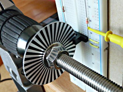 When you know how your disc has to be then make it, fix it on your wheel or whatever you have, adjust the photointerrupter and choose the resistors R1 and R2 as described in the last post. Then test it. Connect the input of your counting device and a voltmeter to OUT and GND and turn the wheel slowly by hand. You must get good logical LOW and HIGH values so they can be properly recognized by your digital logic device. When you don’t get real LOW and HIGH no matter which resistors you choose you probably have too much ambient light, you need more contrast on your disc or your stripes and spaces are too slim.
When everything turns out good connect a scope instead of the voltmeter. Run your machine at full speed and check on the scope if you still reach safely the HIGH and (!) LOW values. If everything is fine then your hardware is ready to run.
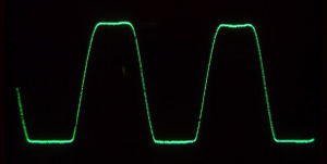 The picture above shows a very basic test of the rotary encoder. The index disc is made with a CD cover, adhesive transparency sheet and a laser printer. The width of the stripes and spaces is 2.5mm, slit width is 1mm. R1 is 1kΩ and R2 is 2.2kΩ. The picture on the left shows the output signal. This is how it should look like. You can see the rise and fall time of the pulses due to the transition of the stripes through the slit of the photointerrupter. It turned out that decreasing R1 (=increasing the LED current) doesn’t give a good HIGH signal because then enough light goes through the black stripes to open the phototransistor a little.
This rotary encoder gives you pulses when the wheel or what you have is turned but it disregards the direction of turn. The counter connected to the encoder always counts forward no matter if you wheel turns forward or backward. When your application has only one direction this simple encoder is good for you. In the next post you can see how to get information about direction. This will make your counter able to run back and forth. You can also find something about the software side when using a arduino.
Enjoy
heliosoph
cool article i loved it..
“It turned out that decreasing R1 (=increasing the LED current) doesn’t give a good HIGH signal because then enough light goes through the black stripes to open the phototransistor a little.”
Why not just print the strip pattern twice on the same sheet to increase the toner density (assuming toner on toner works)? Or print the pattern on two disks and align them.
Regardless, interesting, but unfortunately not exactly what I was looking for
It’s probably a good idea to print the pattern twice and then align the two. I also thought about cutting the pattern from black paper or thin cardboard using a laser cutter but I didn’t have the possibility to do so.
Best regards
heliosoph
Do you know a company that we can prototype this kind of encoder? Any suggestions are highly appreciated.
Thanks.
First of all I would look what’s on the market. There is a big variety of these encoders available. This is much easier than developing one of your own.
Best regards
heliosoph
what about the schematic it is not given
In the post you can find a link to this place where the schematic is described in detail.
regards
heliosoph
Hi thank you for posting can i use it for my project raspberry pi?
Sure you can. You can also transfer the code to python or whatever programming language you use on your pi.
heliosoph