
National Semiconductor
So this is a very easy one – most of the time. There are already many blog posts and forum posts about connecting a LM 35 temperature sensor to an arduino like here, here or here. So why writing another one? When beginning with my LM35 I thought the same and this is why I decided to take this special sensor. But things don’t always work as easily as it looks from a distance. There are some details I found and this is why I write this post.
The basics
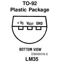
LM35 is a linear temperature sensor with the output voltage calibrated in centigrade celsius. 1 degree celsius makes an output voltage of 10mV. So when you have room temperature at 22°C the LM35 gives you a voltage of 220mV = 0.22V. The sensor has only 3 pins: Vcc which can be between +4V and+20V, GND and Vout. So you connect Vcc to +5V on your arduino board and GND to GND and you have the sensor powered up. Then connect Vout to one of the analog inputs of the arduino and you are done (in many cases – see below). No additional hardware needed!
National Semiconductor
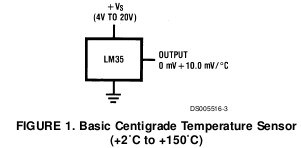
All the schematics in this post are taken from the national semiconductor data sheet of the LM35 that you can find here. When you connect the LM35 as shown on the left the lowest temperature you can measure is +2°C. The LM35 can also measure temperatures down to -55°C but you will need some additional components for that as shown in the data sheet.
The software side is easy: read the analog input scale the value and put it out the way you want!
Improving accuracy
You can improve accuracy of the analog to digital conversion by changing the reference voltage. The arduino reads 10 bits which means 1024 steps. The reference voltage gives the maximum of the input range. By default the reference voltage is set to +5V. You can change to an internal reference that gives 1.1V. Then 1.1V is your maximum input voltage. This fits very well to the output voltage of the sensor and so you can measure from +2°C to +110°C. You don’t need this in terms of resolution but the 1.1V reference is more precise. And it is always better to use the full input range of an AD converter in terms of noise reduction. The code for reading the temperature every second and putting it out to the serial monitor is quite short and simple:
// the pin where the analog data is read
const int analogPin = 0;
// the variable for the data
float sensorValue = 0;

void setup()
{
  // setting the reference voltage
  // to internal 1.1V
  analogReference(INTERNAL);
  // starting serial
  Serial.begin(9600);
}

void loop()
  {
  // read the data and
  // scale it from 10 bit to 0.01 / degree C
  sensorValue = float(analogRead(analogPin)) * 110 / 1024;
  // output data to serial monitor
  Serial.print("temp: ");
  // print only one decimal place
  Serial.print(sensorValue, 1);
  Serial.println("degrees C");
  // wait one second then start again
  delay(1000);
}
Preventing swing on the output of the sensor
National Semiconductor
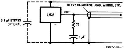
When you don’t want the sensor to be directly beneath the arduino board you take a cable to connect from the sensors location to your arduino. The cable should have a shield to keep away all the high frequency electric noise you get from computers mobile phones and other electronic stuff. Connect the shield to GND on the arduino side of the cable. Not (!) on the sensors side. This is the normal way to do it and you should do this the same way. 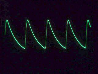 Now here a new problem can occur that is not even documented in the data sheet (although you find the solution there). Whats happening is that the LM35 can begin to swing because of the capacitive load that comes from the cable (especially from the shield). This happened to me although the cable was only around 1m long. When you connect the input pin of your arduino to a scope you can see something like in the screenshot you see on the screenshot (scope at 10μs/cm and 50mV/cm). I measured a swing frequency around 50kHz with an amplitude of 170mV. So this will make serious problems. The temperature value that your arduino reads goes up and down around 10 degrees all the time. This also indicates you a swing. The solution is a resistor in series with a capacitor between Vout and GND directly at the sensors pins. The data sheet proposes a resistor of 75Ω and a capacitor of 1μF. You can also take a 68Ω resistor which is more common. The value is not critical. Check the polarity when you take an electrolytic capacitor. If you still have problems you can try the additional bypass capacitor. In my case there was no need of. The swing problem was the reason I wrote this post because it took me a little while to find out what it is all about.
So this is what I think you need to get good results out of your LM35. Happy measuring!
heliosoph
Hi,
I have run this code exactly but it just showed on screen 109.9 C all the times. I do not know what’s has gone wrong with my Duino board. I am very grateful to get your comments. Thanks.
Hi,
first of all I would check if the hardware is wired correctly and running. Take a voltmeter and measure the output voltage of the LM35 (betwwen Vout and GND). So you see if the sensor is working correctly. Then measure the input voltage at that input pin of the arduino that is read by the script. This has to be the same voltage 🙂 When you have a scope check if the input voltage has a swing as described in the post. When everything is ok then your hardware is wired up correctly. Please report what you found out. Then we can look further.
Best regards
heliosoph
amazing, it works perfect…. im using PIC16f877a without delay… thanks
On my National Semiconductor data sheet the second paragraph, page 5 “Capacitive Loads” deals directly with that topic… I remember because it got me about 20 years ago.. With a different controller, PIC16C71.
The A/D measurements sometimes (I made 100 boards the first run) were erratic and after much head -scratching I did what all good engineers do… I read the data sheet again. Finding that, suddenly I remembered this in a review of the components used in the design… I’ve never forgotten that mistake (Wish it was the only one…) and thank you for taking me back… I just wanted to share that even the professionals make those errors… Not to say “I told you so” or some such stuff. I remember adding the part even though the prototype design hadn’t been tested with one. I was able to change the nomenclature to Ju, remove all 100 caps and when asked point out that is was a jumper… to signal the controller that there was no temp sensor as a ‘future mod” was to use a diode in the IC to measure temperature and save some money.
Doc
Thank you very much for sharing this story! I think this is a rather common but also unknown way how new features sometimes come into existance 🙂
heliosoph
If you use a LM34 you can get without further amplification a much wider temperature range.
This is what I do:
The LM34 GND pin gets connected to a 1N4148 Diode to ground and biased through a Port pin from the uC. This produces about 0.7V offset from Gnd. This voltage is also applied to another analog input channel of the uC ADC. The output pin of the LM34 is connected to ground via a18K resistor. This output voltage connects to the other ADC input channel. In addition, I use an external voltage reference of 2.5V. The uC VREF is proggrammed to use EXT VREF.
Now, you simply read both ADC channels and subtract the offset value to gain the actual LM34 voltage. This method will give you a temperature range from -55 to about 192DegF. Conversion to DEGC is no big effort.
To get better than 0.1deg resolution, run the ADC subsystem in an an automatic acuisition mode and average 64 readings. This effectively increases the 10-bit ADC resolution bits to about 12 bit. Running the ADC automatic creates practically no teal overhead to the uC.
Simply setup the ADC ISR to add up 64 readings and then divide the big number by 64 and add 32 to compensate for 1/2 LSB error. This way you get nice stable temperature readings with 0.1 DegC resolution.
Regards,
Gerhard
Very good hint! Thanks!
Regards
heliosoph